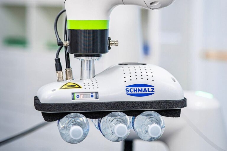
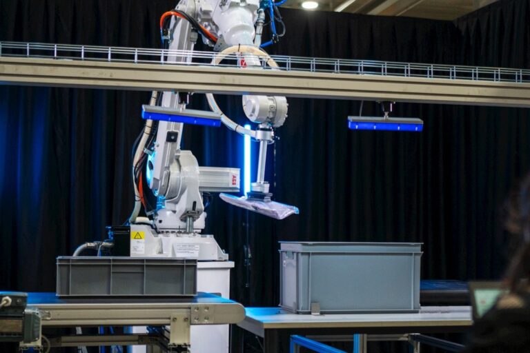
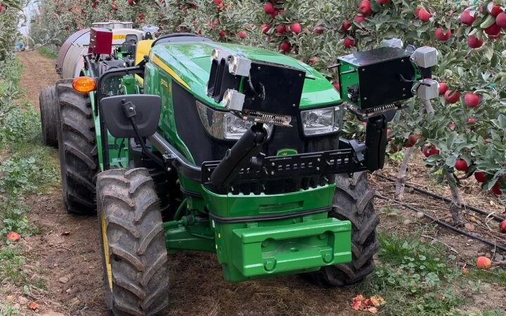
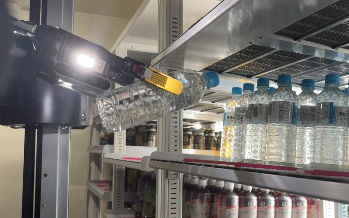
Robot conveyor tracking connects object detection and movement feedback with a feasible handling action inside the available working window. Photo: ABB Robotics
Learn how robot conveyor tracking connects encoders, vision and timing, with practical examples for picking windows, capacity, object queues and recovery.
Robot conveyor tracking keeps a robot’s motion coordinated with material moving on a conveyor. Instead of treating a detected part as stationary, the control system updates its position as the belt advances, allowing the robot to approach, pick or process it within a defined working area.
This guide builds on our coverage of machine vision and motion planning. It explains the relationship between detection, encoder feedback, timing and physical handling, with calculations that help identify practical limitations.
Key Takeaways
Connect every detected object to a known conveyor position and coordinate frame, because a correct image measurement becomes stale as the material moves between sensing and picking.
Evaluate the available tracking window against the complete handling sequence, including acquisition delay, approach, grip confirmation, withdrawal and placement, rather than comparing belt speed with robot speed alone.
Validate starts, stops, changing speeds, missed objects and recovery using representative products, while keeping ordinary tracking logic separate from the application’s protective functions.
Choose Between Indexed and Continuous Handling
An indexed conveyor stops or presents material at controlled intervals. The robot performs its task while the relevant part remains stationary. Continuous tracking instead coordinates robot motion with a moving target.
Continuous operation can avoid some stop-and-start delays, but adds sensing, synchronization and scheduling requirements. It is useful only when those additions improve the complete process.
Compare both arrangements using actual production needs. If the robot must wait for a downstream fixture regardless, keeping the upstream belt moving may simply create a more complicated queue.
Universal Robots’ tracking guide describes adjusting robot paths to conveyor movement. The supported behavior and configuration depend on the specific controller, software and installation.
Understand the Information Chain
A typical workflow detects an object, records its relationship to conveyor movement, calculates its current location and selects an eligible robot action. After gripping, the object leaves the belt’s moving reference and must be handled according to the robot’s actual possession state.
Detection may come from a photoelectric sensor, vision system or another upstream process. A simple sensor can identify an arrival event; vision can add position, orientation or classification when the application needs them.
The encoder measures movement of the mechanism to which it is coupled. It does not automatically prove that a loose part moved the same distance. Slip between the measured motion, belt and object can create errors.
Document each interface from sensor to robot controller, including the object identifier, measured pose, conveyor position and data validity. A communication link alone is not a complete tracking specification.
Calibrate Distance and Direction
The controller needs a relationship between encoder counts and physical travel, plus the direction of that travel in the robot’s coordinate system.
In an illustrative calibration, a measured 0.5 m belt movement produces 2,000 decoded counts. The scale is 4,000 counts per meter, or 0.25 mm per count. Confirm what the controller means by a count, since pulse and decoding conventions can differ.
Universal Robots’ setup documentation distinguishes incremental and absolute encoders and describes quadrature feedback for speed and direction. Use the supported electrical and timing specifications for the installed hardware.
Verify scale and sign over multiple travel distances. A short move that appears correct may hide a proportional error that becomes significant farther downstream. Our calibration guide explains the broader coordinate relationships.
Associate Detection With the Right Position
An image describes a scene at acquisition time. The robot may receive the processed result later, after the object has traveled farther along the belt.
Associate the observation with an appropriate encoder position or synchronized timing reference, using the controller’s supported method. Do not assume that the position recorded when a network message arrives is the position at which the image was taken.
Cognex’s encoder explanation describes pulses as an indication of conveyor-related motion. The application still has to connect that movement information with the relevant object observation.
Check object identity through the pipeline. If two parts pass the camera close together, a delayed result must not be assigned to the wrong arrival event or reused after its target has already been collected.
Calculate the Effect of Delay
Suppose a conveyor moves at a constant 0.4 m/s and a result arrives 75 milliseconds after image acquisition. During that interval, the part travels 0.4 x 0.075, or 0.03 m: 30 mm.
That displacement is not necessarily an error if tracking correctly accounts for it. It becomes an error when the application uses the old image position as though the part were still there.
Delay variation matters too. At the same speed, an uncompensated timing uncertainty of 10 milliseconds corresponds to 4 mm of travel. This is an illustrative relationship, not a complete accuracy estimate.
Measure acquisition, processing, communication and command timing separately where possible. An average latency may conceal occasional long delays that cause missed picks, especially near the end of the available working window.
Define the Usable Tracking Window
The useful window is the part of conveyor travel in which the complete action is feasible. It depends on arm reach, tool orientation, surrounding equipment, collision clearance and the permitted entry and exit behavior.
If a hypothetical usable region is 0.8 m long and the belt moves at 0.4 m/s, an object spends two seconds in that region. Some of that time may already be consumed by detection, scheduling and approach.
Define the latest point at which a pick can start and still finish correctly. A target remaining geometrically reachable does not establish that the gripper can seal, confirm possession and clear the belt in time.
Use the complete tool and carried-part geometry. Our robot-arm guide explains why nominal reach and payload are only part of application selection.
Schedule Objects the Robot Can Actually Handle
A robot may see more candidates than it can collect. Define eligibility based on object type, pose, remaining window, destination availability and the current robot state.
Choosing the nearest object is not always the best rule. An object farther downstream may expire sooner, while a nearer object may require an awkward grasp or unavailable destination.
Define what happens to uncollected material: downstream handling, recirculation, a reject route or another approved process. Missing a pick should produce a known outcome rather than an untracked accumulation.
For multiple robots, assign ownership so two machines cannot act on the same target. Record when ownership begins, how it is released and what occurs if the first robot abandons the attempt.
Check Complete-Cycle Capacity
Consider a robot with an illustrative complete handling cycle of 1.5 seconds, including return and placement. Its ideal capacity is 40 cycles per minute before interruptions or other losses.
A belt carrying one part every 0.2 m at 0.4 m/s presents 120 parts per minute. One robot with that assumed cycle cannot collect every object, even if its individual tracking movement looks fast enough.
Possible process changes include spacing control, additional robots, a different handling sequence or a reduced arrival rate. Evaluate them against the actual constraint rather than increasing belt speed by default.
Our ROI guide connects capacity with useful output. Include rejected products, recovery labor and downstream limitations when comparing layouts.
Plan Stops, Restarts and Lost Data
A conveyor stop changes the timing assumptions. A restart may occur with objects already in the detection queue, and a reversal can invalidate a queue designed only for forward travel.
Use supported controller behavior and define the application’s response to each event. Record which queued objects remain valid and when a fresh observation is required.
Encoder loss, stale vision data and controller restart also need explicit handling. An old object position should not silently become a fresh command after communication resumes.
Our integration guide explains requests, acknowledgments and state reconciliation. Apply those principles to both the robot task and the physical material still on the conveyor.
Validate the Physical Pick
Start with the intended product family and a controlled test plan. Verify static calibration and detection first, then evaluate tracking and the complete sequence at supported operating conditions.
Cover representative belt speeds, product spacing, object orientations and ordinary starts and stops. Use approved procedures for interruption tests and the protective measures required for the integrated application.
Test area
Question
Useful evidence
Position
Does the target remain correctly located?
Observed error across the tracking window
Handling
Is the intended object acquired and retained?
Confirmed picks, damage and dropped items
Capacity
Can the workflow meet arrival demand?
Accepted output, missed targets and queues
Recovery
Are interrupted objects reconciled?
Known states and measured intervention time
Compare accepted output with all eligible arrivals, and distinguish missed targets from failed grasps. Our acceptance guide explains how to preserve those denominators and test conditions.
Maintain the Tracking Configuration
Retain encoder scale and direction, camera calibration, trigger configuration, conveyor frames, tracking limits, queue rules and the accepted program revision.
Investigate changes in missed-pick patterns before simply shifting targets. A worn measuring wheel, belt slip, camera movement or delayed message can each require a different correction.
Review affected tests after mechanical or software changes. Our maintenance guide explains how configuration history supports diagnosis.
Dependable conveyor tracking connects current information with a feasible physical action. Its value appears in complete accepted handling cycles and understandable exceptions across the intended flow of material.
Keep Tracking Separate From Protective Control
The encoder and object queue support the handling task. They should not be assumed to provide the protective functions needed for the robot, conveyor and neighboring machinery.
Assess access to moving equipment, pinch points, the carried object and the consequences of a missed or dropped part across the integrated application. Qualified personnel should establish and validate the required protective measures using the applicable manufacturer and site procedures.
Our safety guide covers the wider assessment. Include protective stops and their approved reset sequence in the integration review, without treating an ordinary tracking pause as equivalent evidence.
Frequently Asked Questions
What is robot conveyor tracking? It coordinates robot motion with conveyor movement so the robot can act on moving material within a supported working region.
Does every application need vision? No. A sensor may suffice when object location and orientation are otherwise constrained. Vision is useful when the task needs additional pose or identification information.
Why use an encoder? It provides conveyor-related movement feedback. The system must still calibrate that movement and associate it with the correct detected object.
Can tracking compensate for belt slip? Only to the extent the sensing and controller arrangement observes the relevant movement. Measuring a drive shaft does not automatically measure a loose object slipping on the belt.
Is faster robot motion enough? No. Capacity also depends on detection, object spacing, the usable window, gripping, placement and recovery across the full cycle.
What should be tested after a camera move? Review calibration, object localization and the affected tracking and handling tests before accepting the changed configuration.
XPENG will demonstrate its latest IRON humanoid at AI Day in Guangzhou on November 25, putting on-device physical AI alongside robotaxi and mobility updates.