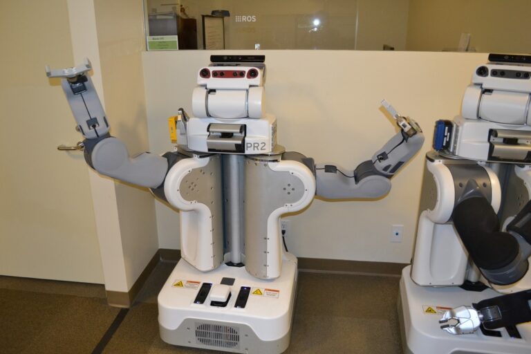
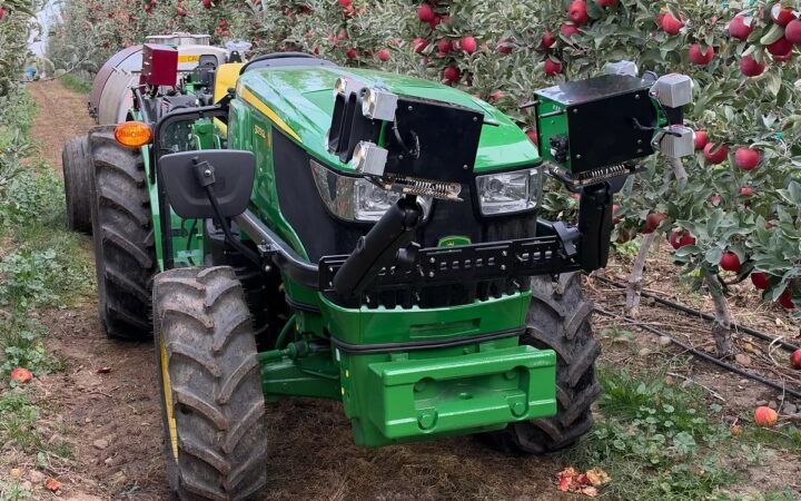
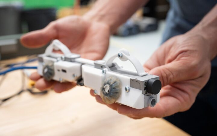
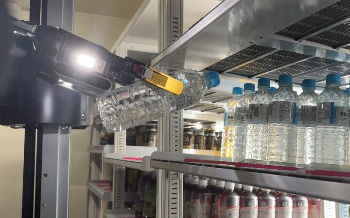
Mobile manipulators combine navigation and object handling, with reliable work depending on positioning, gripping and complete-system coordination. Photo: Oleg Alexandrov / Wikimedia Commons
Learn how mobile manipulators combine navigation and object handling, with practical guidance on positioning, gripping, stability, recovery and deployment testing.
Mobile manipulators combine a mobile base with a robot arm, allowing one machine to travel between locations and handle objects when it arrives. The base brings the arm to the work; the arm performs actions such as picking a component, loading a fixture or placing a container.
This guide connects our coverage of mobile robots and robot arms. It explains how to choose a suitable task, coordinate movement and manipulation, and judge performance across a complete operating cycle.
Key Takeaways
Evaluate mobile manipulators as complete systems whose useful capacity depends on arm reach, tool and object loads, base stability, station access and the ability to recover from interrupted work.
Separate navigation to a workstation from accurate manipulation at that workstation, using verified positioning, current perception and calibrated coordinate relationships before the arm begins its task.
Validate full missions across representative objects and operating conditions, measuring accepted deliveries, intervention time and system availability rather than relying on isolated driving or grasping demonstrations.
What Is a Mobile Manipulator?
A mobile manipulator has a moving platform, a manipulation mechanism and an end-effector such as a gripper. Sensors, control software, computing and power connect those parts into a machine capable of changing both its location and its surroundings.
The architecture varies. An industrial system might mount an articulated arm on an autonomous mobile robot. A service or research platform might use a lifting column and telescoping arm. Some designs have two arms, but two arms are not required for mobile manipulation.
PAL Robotics describes TIAGo as a modular platform combining perception, navigation and manipulation. The original Stretch design instead uses a differential-drive base, lift and telescoping arm, as documented in its research paper. These examples show how different mechanical choices can address the same broad problem.
The important question is whether a particular configuration can complete the intended workflow reliably. A product demonstration establishes what happened in that demonstration; deployment requires evidence for the actual objects, stations and operating conditions.
When Bringing the Arm to the Work Makes Sense
Consider tasks distributed across several stations: collecting sample trays, replenishing machines or moving components between a shelf and a workstation. Mobility can let one manipulation system serve more than one location.
That flexibility has a cost. Travel, positioning and coordination consume time that a fixed arm could spend handling parts. An AMR delivering standardized totes to a stationary robot may be a better arrangement when handling demand is concentrated at one busy station.
Compare three process designs before selecting hardware: people moving material to a fixed robot, mobile transport feeding fixed automation, and a mobile manipulator visiting workstations. Estimate complete output and support effort for each.
Start with a bounded task. A defined family of trays at known shelves is easier to specify and evaluate than “handle anything anywhere.” Expansion can follow evidence that the first workflow works.
Specify the Object and Station Together
Record object mass, dimensions, surface, stiffness and permitted gripping areas. Include changes such as a container becoming heavier when full or a transparent lid affecting perception.
Then survey the station: working height, approach space, door position, fixture geometry and possible obstacles. A reachable object may still be impossible to grasp because the wrist cannot enter the required orientation or withdraw without a collision.
Requirement
What to establish
Evidence to collect
Object handling
Grip locations, load variation and acceptable damage
Representative parts and grasp trials
Station access
Approach, working pose and withdrawal clearance
Measured geometry and reach checks
Transport
Supported carrying position and load retention
Approved loaded-route trials
Completion
Correct object accepted at the destination
Placement confirmation and task record
Use the gripper guide to connect contact design with object variation. Small station changes, such as consistent tray presentation, can remove substantial perception and motion-planning difficulty.
Choose a Base Pose That Leaves the Arm Room to Work
The shortest driving route does not necessarily end at a useful manipulation position. Base placement determines which targets the arm can reach and how much room remains for its joints, tool and carried object.
Check the whole sequence from one proposed stopping position: approach the object, grasp it, lift clear, move to a carrying pose and later place it. If several arm poses sit near their limits, moving the base slightly may produce a more robust sequence.
Distinguish two operating strategies. In stop-and-manipulate operation, the base remains stationary while the arm works. Coordinated operation moves the base and arm together. The latter introduces additional planning, control and validation demands; it should be a supported capability, not an assumption made from separate base and arm specifications.
Our motion-planning guide explains why reaching a target position and executing a feasible path are separate requirements.
Connect Navigation With Local Positioning
Navigation brings the robot into the station area. Manipulation may require a more accurate estimate of the relationship between the tool, object and fixture than the global map alone provides.
Possible approaches include local visual markers, observing the fixture directly, mechanical docking or supported combinations. Select the method around the required tolerance and environment, then measure its performance after repeated arrivals.
Coordinate frames describe positions relative to different references. The ROS frame conventions distinguish the robot base, a locally continuous odometry frame and a global map frame whose localization estimate can change. An object pose also needs a known relationship to the camera and tool at the relevant time.
Our calibration guide covers these relationships. A stale image or incorrect camera mounting transform can produce a precise movement toward the wrong physical location.
Account for the Complete Load and Stability
Arm payload, mobile-base capacity and whole-system stability answer different questions. Include the gripper, adapters, cables and object when evaluating the arm; include installed equipment when evaluating the base.
Load position matters as well as mass. In a simplified static example, a 2 kg object held 0.5 m horizontally from a tipping edge creates about 9.8 newton-metres of gravitational moment around that edge: 2 x 9.81 x 0.5. This calculation excludes the arm, tool, acceleration, floor slope and other contributors, so it cannot establish a safe payload or operating limit.
Use the supplier’s approved loading and motion envelope for the complete configuration. Confirm permitted carrying poses, floor conditions, acceleration and any restrictions on manipulating while the base moves.
The Stretch RE1 manual explicitly discusses toppling and the possibility of the arm pushing or pulling the robot over. That warning concerns a particular research platform, but illustrates why an arm’s force capability cannot be evaluated independently of its support.
Keep the Robot’s World Model Current
Planning needs a useful representation of the robot and surrounding objects. A station that was clear on arrival may change when a person opens a door, another cart parks nearby or the robot picks up a bulky container.
MoveIt’s planning scene supports collision and constraint checking for the robot and its environment. In a mobile-manipulation application, the implementation must also maintain an appropriate representation of carried objects and changing surroundings.
Check whether sensing covers the arm’s working volume, the base’s route and the loaded robot’s actual envelope. A low navigation scanner does not automatically describe overhead shelves or an object protruding beyond the chassis.
These planning functions support task execution. Protective functions require their own appropriate design and validation across the integrated machine; see our safety guide.
Define Task States and Recovery
A useful task sequence might be: travel to pickup, establish the working pose, identify the object, grasp, confirm possession, stow for transport, travel to delivery, place and confirm acceptance.
Each transition needs evidence. Closing the gripper does not prove that the intended object was acquired. Reaching the delivery station does not prove that the object was released into the correct location.
Define recovery for a missed grasp, obstructed station, dropped communication or uncertain object identity. Use bounded retries with a clear stopping condition and an assigned operator response. Repeating a failed motion without understanding the current state can worsen the problem.
Keep task identity through restarts. If the destination received the object but its acknowledgment was lost, the system should reconcile the physical result before attempting another delivery. Our integration guide explains these handshakes in more detail.
Calculate Output Across the Whole Mission
Consider an illustrative mission requiring 40 seconds of travel to pickup, 15 seconds of positioning, 25 seconds of picking and stowing, 50 seconds of loaded travel, and 30 seconds of delivery and confirmation.
The total is 160 seconds. Dividing 3,600 by 160 gives a theoretical maximum of 22.5 completed missions per hour for that assumed sequence, with no queues, charging, faults or additional repositioning.
If a planning scenario reserves 15% of each hour for other activity, it leaves 3,060 seconds and about 19.1 missions per hour at the same cycle time. The 15% figure is an assumption to test, not a typical industry allowance.
Measure the actual time distribution during a pilot. Long recovery delays and a congested station may matter more than a small improvement in nominal grasp speed. Our fleet-management guide covers shared resources and competing missions.
Run a Pilot That Exposes Variation
Agree acceptance criteria before the demonstration: completed missions per shift, acceptable placement quality, intervention frequency, recovery time and operating availability. Define whether a manually rescued mission counts as autonomous completion.
Test representative object variants, shelf positions, arrival offsets, lighting and battery conditions within the supported operating envelope. Include approved interruption and recovery tests, with people responsible for supervising them.
Log timestamps for navigation, alignment, perception, grasping, transport, placement and recovery. Separate failures by cause so a localization issue is not mistaken for a gripper problem.
Include support labor in the business case. For example, 12 interventions lasting four minutes each consume 48 minutes of direct assistance, before any walking or task resumption time. Our ROI guide explains how to connect operating evidence with realizable benefits.
Expand From a Repeatable First Task
Begin with a limited object family, clear stations and a defined route. Establish dependable completion and understandable exceptions before introducing additional workstations or more varied objects.
Record the accepted hardware, tool, calibration, maps, software and task parameters at handover. Assign responsibility for changes and repeat affected validation when a fixture, load, camera or route changes.
Mobile manipulators are useful when movement and handling solve a specific workflow together. The strongest deployment case comes from repeatable end-to-end results and a practical recovery process across the intended operating conditions.
Frequently Asked Questions
What is a mobile manipulator?
A mobile manipulator combines a moving base with an arm or other manipulation mechanism and a tool, allowing it to travel and handle objects at different locations.
How is it different from an AMR?
An AMR principally provides autonomous movement. A mobile manipulator adds an arm and handling capability; an AMR carrying a tote is not necessarily a mobile manipulator.
Can a mobile manipulator work while driving?
Some systems support coordinated base-and-arm movement, while others use stop-and-manipulate operation. Verify the complete configuration’s supported capabilities and operating restrictions.
Does a collaborative arm make the whole robot collaborative?
The integrated application still needs assessment and validation, including base motion, tools, loads and the surrounding workspace. The arm’s designation alone does not establish the complete system’s permitted use.
How accurately must the mobile base stop?
The requirement depends on the task and subsequent alignment method. Define the tolerance at the object or fixture, then verify how navigation, docking, perception and arm control achieve it together.
What should a first pilot measure?
Measure complete accepted missions, placement quality, interventions, recovery time and availability across representative conditions, alongside the time spent in each mission stage.
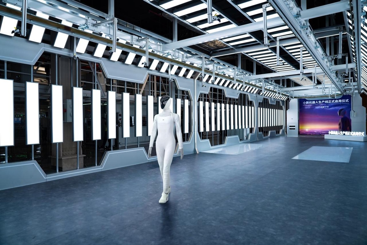
XPENG will demonstrate its latest IRON humanoid at AI Day in Guangzhou on November 25, putting on-device physical AI alongside robotaxi and mobility updates.