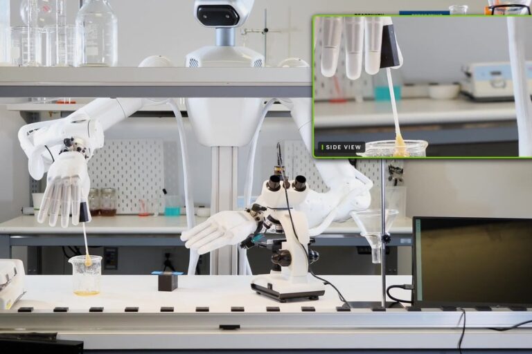
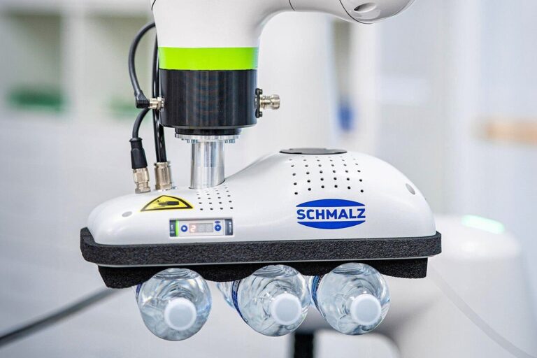
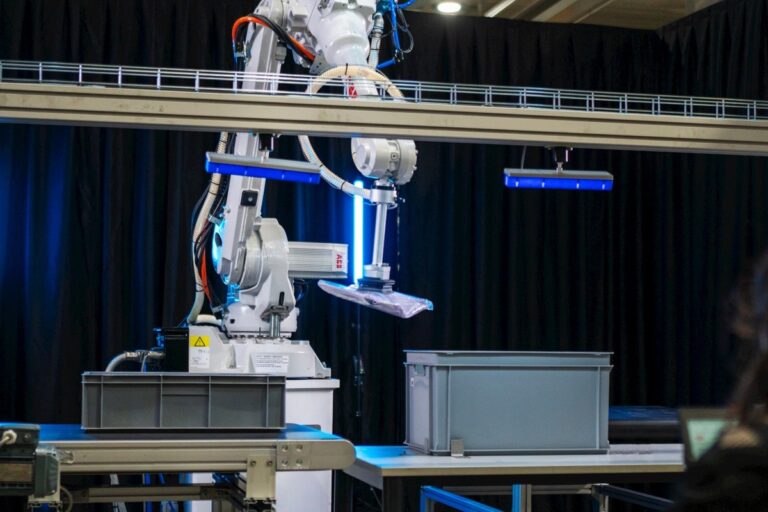
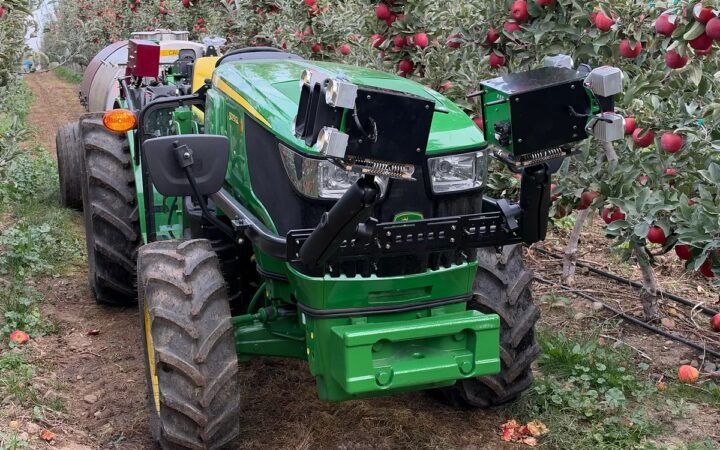
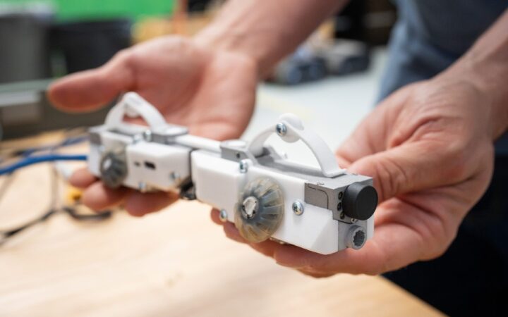
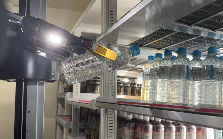
Reliable robot vacuum gripping depends on the product surface, loading, vacuum supply and verified pickup and release across the complete cycle. Photo: FANUC / Schmalz
Understand robot vacuum gripping, from effective suction area and loading to leakage, evacuation time, grip confirmation, release and complete-tool validation.
Vacuum gripping uses a pressure difference to hold an object against a suction interface. On a robot, that interface is part of a complete handling system: cups or foam, a vacuum source, tubing, valves, monitoring and a tool structure that must work with the real product throughout the motion.
This guide extends our gripper guide with practical detail on suction, leakage, loading, release and validation. The objective is repeatable handling under defined conditions, with enough information to diagnose a missed pickup or deteriorating seal.
Key Takeaways
Size vacuum gripping around the complete load case and actual contact surface, because nominal cup diameter and a maximum vacuum figure do not establish usable holding capacity during robot movement.
Evaluate leakage, evacuation time and flow together, using representative products and the installed tubing and valves rather than relying on a vacuum generator’s headline specification.
Confirm possession and release with application-appropriate evidence, define the response to vacuum loss and validate the entire handling cycle before accepting production performance.
Understand How Suction Holds an Object
A vacuum source reduces pressure in the space bounded by the cup and workpiece. The surrounding air pressure then produces a net force pressing the workpiece toward the suction interface.
Schmalz’s suction-cup explanation expresses ideal holding force as pressure difference multiplied by effective area. The effective sealed area matters; the outside diameter alone is not necessarily the area to use.
A seal can be imperfect. Air may enter around the lip, pass through porous material or leak through the plumbing. The vacuum source and the interface must establish a workable operating condition despite the leakage expected in the application.
Describe pressures consistently. Absolute pressure, pressure difference and a percentage vacuum use different references. Confirm the meaning and units before comparing catalog values or configuring monitoring thresholds.
Start With the Surface and Product
Record mass, dimensions, stiffness, surface finish, porosity and permitted contact areas. Include the range of production conditions rather than use a single favorable sample.
A smooth rigid panel presents a different problem from corrugated cardboard, a flexible bag or a textured molded component. Packaging seams, labels, dust, moisture and wrinkles can change sealing behavior.
Determine whether suction may mark, deform or damage the product. A strong grip is not useful if it crushes a package, lifts only a film layer or leaves an unacceptable surface impression.
Specify where the tool is allowed to touch and how the product may be supported. A controlled presentation fixture can sometimes improve reliability more than a larger pump or a more complicated gripper.
Read Holding Force as One Design Input
Consider an illustrative effective circular area with a 40 mm diameter. Its area is about 0.001257 square meters. At a pressure difference of 60,000 pascals, the ideal normal force is approximately 75.4 newtons.
That is a theoretical calculation, not a rated payload or permission to lift a corresponding mass. It excludes leakage, acceleration, off-center loading, cup deformation and the margins required for the application.
Schmalz’s load calculations address handling orientation and motion. Use the supplier’s applicable design method and verified product data for the complete task.
Document the assumptions used in the selection. If a calculation assumes a clean, airtight surface and the actual product is dusty cardboard, the arithmetic may be correct while its application is unsuitable.
Include Motion, Orientation and Moments
The load on the interface changes as the robot accelerates, turns and reorients the object. A cup holding a horizontal panel from above faces a different loading arrangement when the panel is rotated upright.
For an illustrative 2 kg object accelerating vertically upward at 3 m/s², the required upward force on the object is approximately 2 x (9.81 + 3), or 25.6 newtons, before application-specific margins. This simplified example does not describe lateral motion or rotational loading.
Check the center of mass relative to the cup arrangement. An off-center object can create a peeling tendency or uneven loading, so dividing the total force equally among cups may be unrealistic.
Our robot-arm guide explains payload and loading considerations. Include the tool, adapters, valves and carried object when checking the robot’s supported configuration.
Select the Contact Arrangement
Flat cups, bellows cups and foam gripping surfaces address different geometry and compliance needs. Choose the interface around the product, required positioning behavior and supported load cases.
Compliance can help establish contact on an uneven surface, but it also changes how the held object moves relative to the tool. A successful lift may still produce an unacceptable placement if the product shifts during transport.
For several cups, check whether all intended contacts are present across product variation. A cup positioned over a hole, edge or missing part can become a leakage path that affects the rest of the circuit.
Design question
What to examine
Evidence to seek
Sealing
Surface, seams and contact variation
Repeated pickups on actual products
Loading
Mass, orientation and center of gravity
Supported complete motion envelope
Positioning
Compliance and product movement
Measured placement quality
Circuit behavior
Open cups, leakage and isolation
Pressure and timing across expected cases
Ask the supplier how isolation, zoning or check valves affect the proposed circuit. Their benefit depends on the design and failure condition, rather than their presence alone.
Match Vacuum Level With Flow
Vacuum level describes pressure; flow describes how quickly air is moved. A system may reach a strong vacuum against a sealed surface yet struggle to maintain adequate pressure when handling a porous product.
Schmalz’s generation overview describes technologies with different flow characteristics and notes the difficulty of leakage around folded packaging. Select around the actual operating point, not one maximum specification.
Evaluate tubing length and diameter, connectors, filters and valves as part of the system. The behavior at the cup can differ from the behavior measured immediately at the source.
Test with production samples, including expected surface variation. Record whether the required pressure is reached, how quickly it is reached and whether it remains adequate during the intended motion.
Account for Evacuation Time
The robot needs time to establish the grip before lifting. That time depends on the volume being evacuated, available flow, leakage and the required pressure condition.
Define a meaningful pickup sequence: establish contact, request vacuum, confirm the specified grip condition and only then begin the permitted transport motion. Include a timeout and a known response if confirmation does not arrive.
In an illustrative cycle, reducing approach and departure motion from 0.9 to 0.7 seconds saves little if the system still waits 0.8 seconds for a seal and another 0.5 seconds for placement and release. The complete cycle falls from 2.2 to 2.0 seconds, not by the proportion suggested by motion alone.
Measure the individual stages before changing hardware. A leak, unnecessarily large volume or restrictive connection may explain slow gripping more directly than insufficient robot speed.
Monitor Possession With Appropriate Evidence
A vacuum sensor reports pressure at its installation point. It does not automatically prove that the correct object is held, that every cup is engaged or that two thin sheets were not picked together.
Choose confirmation around the consequences of a wrong or uncertain pickup. The application may need pressure information together with vision, part detection, weight or another supported measurement.
Set thresholds, timing and diagnostics through the supplier’s method and application tests. Keep ordinary process confirmation distinct from any safety-related function and its required validation.
Our sensor guide explains why a measurement needs a defined interpretation. Record what each signal can establish and which failure conditions it cannot distinguish.
Design Release as Carefully as Pickup
Turning off the vacuum request does not establish that an object has separated from the tool. Residual vacuum, flexible material or adhesion can delay release.
Evaluate supported venting or blow-off behavior with the actual product and destination. Excessive or poorly directed air can disturb a lightweight object or nearby material.
Confirm that the destination received the object before the tool departs in a way that could drag it. Include the permitted placement tolerance and the effect of tool compliance.
Our integration guide distinguishes commands from confirmed physical results. Preserve that distinction in both pickup and release logic.
Plan Vacuum Loss and Recovery
Define the expected response to a failed seal, declining vacuum, power loss or unavailable air supply. The response must consider the held load, robot position and surrounding equipment.
Stored vacuum, non-return valves and other measures have design-specific limits. Their presence does not guarantee indefinite retention or make the load safe under every failure condition.
Qualified personnel should establish the application’s protective measures and approved recovery procedures. Do not test loss conditions by creating an uncontrolled dropped-load hazard.
Our safety guide covers application assessment. Record when an operator may retry, when inspection is required and how uncertain material is removed from the workflow.
Validate and Maintain the Complete Tool
Acceptance should cover representative products, motion profiles, orientations, supply conditions and expected contamination. Check pickup, retention, placement quality and release together.
Count failed seals, dropped or damaged parts, double picks and interventions separately. A task eventually completed after several retries is different from a first-attempt success.
Our acceptance guide explains test scope and operating records. Retain cup type, layout, circuit configuration, settings and the tested program revision.
Monitor wear, dirt, damaged lips, loose fittings and filter condition through the supplier’s maintenance procedure. Our maintenance guide shows how failure history helps target inspections.
Reliable vacuum gripping comes from matching the interface, supply and motion to the product. The best evidence is consistent accepted handling across the intended operating range, with understandable exceptions and a controlled response when the grip becomes uncertain.
Compare Energy Over the Actual Duty Cycle
Compare vacuum supply options using the complete operating pattern: pickups, holding periods, releases and idle time. Include the installed compressed-air or electrical supply and any approved energy-saving controls.
A smaller source is not automatically more efficient if it must run continuously to overcome avoidable leaks. Likewise, a high-capacity source may be unnecessary for a well-sealed product and short holding period. Measure consumption alongside gripping time and accepted output, then evaluate improvements without compromising the verified handling envelope.
Frequently Asked Questions
How does a vacuum gripper work? It lowers pressure beneath a suction interface so the surrounding air pressure produces a holding force against the object.
Can cup diameter determine payload? No. Effective area and pressure difference provide an ideal force estimate, while usable capacity also depends on motion, orientation, surface, leakage and the application’s design margins.
Why does porous cardboard create difficulty? Air can pass through the material or around surface features, requiring sufficient flow and a suitable contact interface to establish the intended operating condition.
Does good vacuum prove the right part is held? Not necessarily. Pressure alone may not distinguish object identity, double picks or every contact failure. Select confirmation appropriate to the application.
Why can release take too long? Residual vacuum, adhesion or flexible material can delay separation. Evaluate the supported release arrangement using actual products and the destination.
What should be checked after changing cups? Review geometry, compliance, load capacity, pressure and timing behavior, then repeat affected handling and placement tests before accepting the changed tool.
XPENG will demonstrate its latest IRON humanoid at AI Day in Guangzhou on November 25, putting on-device physical AI alongside robotaxi and mobility updates.