Robot sensors support dependable decisions when measurement, calibration, timing and failure behavior are designed for the actual task. Photo: APJarvis / Wikimedia Commons
Understand encoders, cameras, lidar, IMUs and force sensors, and learn how calibration, timing and failure testing turn robot measurements into dependable actions.
Robot sensors turn physical conditions into information a machine can use. They report joint motion, distance, contact, images and other measurements. A useful sensing system connects that information to a defined action, such as correcting a grip, detecting a missing component or estimating the robot’s position.
Adding more sensors does not automatically make a robot more dependable. The measurements must be suitable for the task, correctly timed and interpreted within their limits. This guide extends our robotics introduction with a practical method for choosing, integrating and testing robot sensors.
Key Takeaways
Select sensors by the physical quantity and operating decision required, then evaluate range, uncertainty, timing and environmental limits together rather than compare resolution alone.
Calibration, mounting, coordinate frames and timestamps determine whether measurements from different devices describe the same physical event consistently.
Define the response to missing, stale or contradictory data, and keep ordinary perception functions separate from protective functions that require a validated safety architecture.
Internal and External Sensing
Internal sensing describes the robot itself. Joint encoders report movement, current measurements help characterize actuator behavior and temperature sensors monitor operating conditions. This information supports control and diagnostics. Our robot arm guide shows how motion feedback fits into manipulator selection.
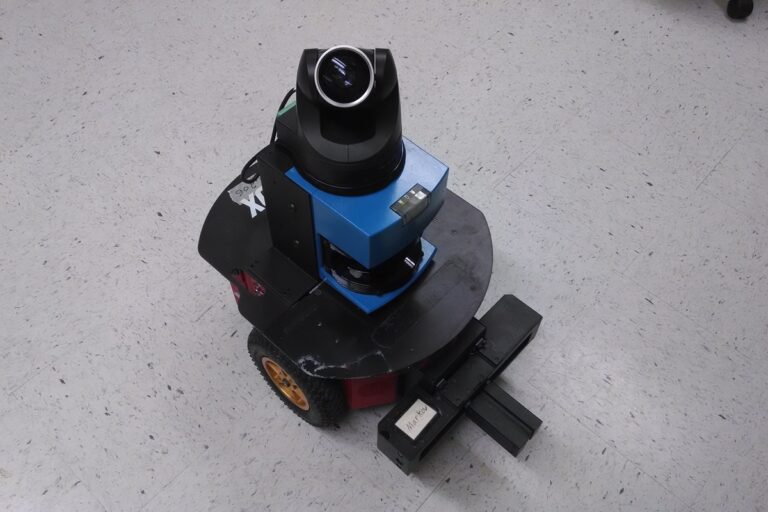
External sensing describes the surrounding world or the interaction with it. Cameras observe parts, lidar measures ranges, proximity sensors detect objects and force sensors measure mechanical loading. A wrist force sensor sits on the robot but measures the interaction between its tool and the task.
The distinction is useful without being absolute. Wheel motion can estimate how far a mobile robot traveled, but the estimate depends on contact with the floor. A camera may observe an external landmark to correct that motion estimate. Understanding what a device directly measures helps avoid asking it to prove something it cannot establish alone.
The Main Sensor Families
Sensor
What it measures
Practical limitation to test
Encoder
Rotary or linear movement and position
Mechanical play, reference state and the relationship between measured and actual motion
Camera or depth camera
Image appearance and, for suitable systems, depth
Lighting, surface properties, occlusion and calibration
Lidar or range sensor
Distance along one or more sensing directions
Coverage, reflectivity, transparent objects and blocked views
IMU
Angular rate and specific force, with orientation estimates in some systems
Bias, vibration, drift and mounting alignment
Force/torque sensor
Applied forces and moments
Overload, tool weight, acceleration and compensation
Proximity or contact sensor
Presence or a local physical condition
Target material, sensing distance and what a positive signal actually confirms
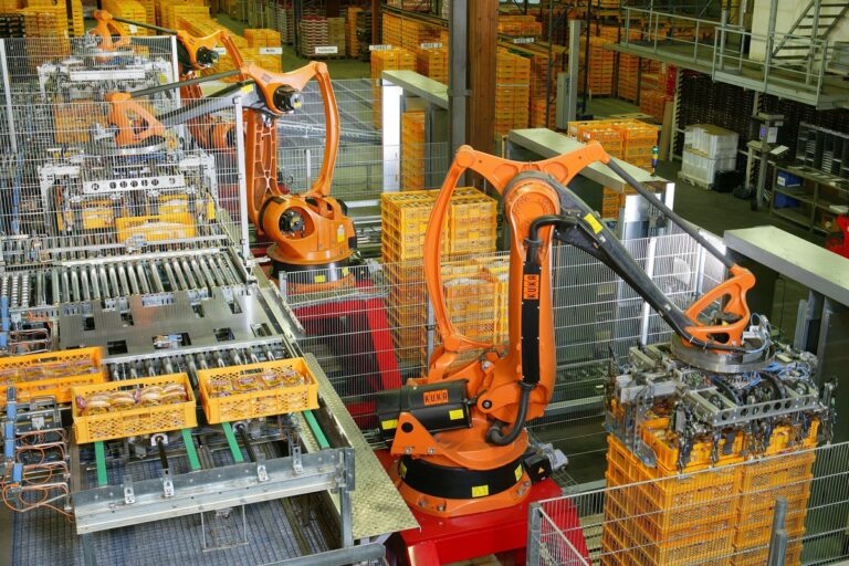
A task often needs several of these devices. A handling cell might use vision to locate a part, encoder feedback to move the arm, a pressure sensor to check vacuum and a presence sensor to confirm delivery. Assign a specific purpose to each signal.
Encoders: Motion Is Not Always Position in the World
An incremental encoder reports changes in movement, while an absolute encoder identifies position within its encoded range. SICK’s encoder overview explains these families and their use in motion measurement. Startup reference requirements depend on the device and system design.
A motor encoder can provide excellent feedback for the motor shaft without directly proving where a remote mechanism ended up. Gear compliance, backlash, belt behavior or coupling damage may affect the relationship. Determine whether the application needs measurement at the actuator, at the output or at both.
For a wheeled robot, counting wheel rotation gives an estimate of travel. Slipping wheels and an inaccurate wheel diameter can make that estimate drift from the robot’s actual path. The AMR guide explains why navigation must be evaluated in the real facility.
During commissioning, check known movements and reversals, then repeat them under representative loading. Keep reference procedures and configuration values with the machine documentation so maintenance does not silently change the meaning of the measurements.
Cameras and Depth Sensors
A conventional camera records image intensity and color information. A vision application uses that data to identify, inspect or locate something. A depth system adds a method for estimating distance, such as stereo geometry, structured light or time of flight.
These approaches have different operating constraints. A scene with little useful visual texture can challenge stereo matching, while reflective surfaces can complicate some active depth measurements. Test the actual target and background instead of treating a clean sample image as a specification.
Field of view, working distance and mounting position determine what the camera can observe. An object can be within the nominal range yet hidden behind a tool or another item. Build coverage around the complete sequence, including approach and withdrawal.
Our machine vision guide covers lighting, calibration and inspection testing in depth. For sensor selection, first write down the required decision and the smallest important feature or positional difference.
Lidar and Other Range Measurements
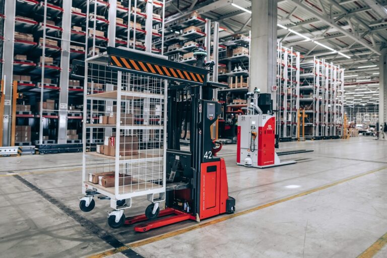
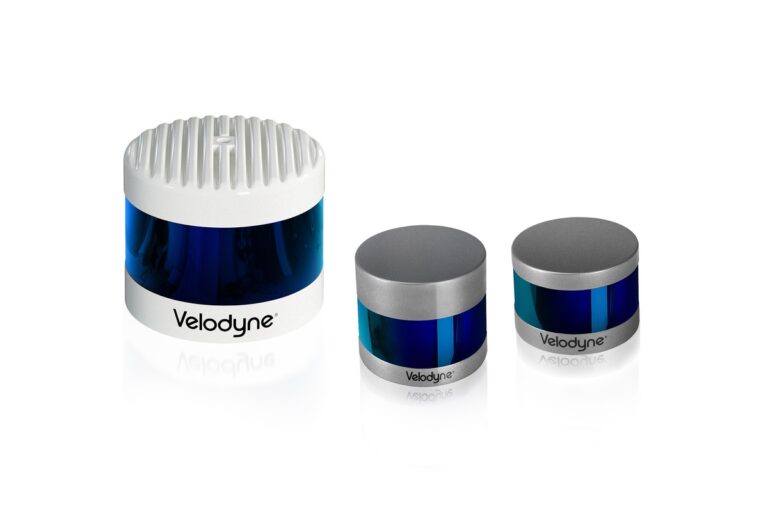
Lidar uses emitted light and received returns to estimate distance. A scanning device measures in multiple directions, producing a profile or point cloud that software can use for mapping, localization or obstacle detection. Sensor geometry determines which parts of the scene are sampled.
A planar scanner observes a slice through the environment. An obstacle above or below that slice may be absent from its measurements. A three-dimensional sensor expands coverage, but still has blind spots and occlusion. Draw the sensing volume beside the robot and its expected obstacles.
Transparent panels, dark targets, reflective metal, airborne material and ambient conditions can affect different range sensors differently. Include the relevant cases in the evaluation. “Maximum range” does not establish dependable detection for every material throughout that distance.
Ultrasonic and optical proximity devices can provide simpler local distance or presence information. They may be appropriate for a narrowly defined detection point even when the robot also carries a richer perception system. Complexity should follow the information requirement.
IMUs: Helpful Motion Data With Accumulating Error
An inertial measurement unit commonly combines accelerometers and gyroscopes. Gyroscopes measure angular rate; accelerometers measure specific force. Some products also provide processed orientation information or include additional sensing.
Integrating imperfect rate measurements introduces accumulating error. Analog Devices’ gyro explanation describes bias-related drift and how complementary measurements can help. An IMU should not be assumed to provide an indefinitely accurate indoor position simply because it reports at a high rate.
Mounting alignment and vibration matter. A sensor on a flexible bracket can observe motion that differs from the rigid robot model used by the estimator. Temperature effects and startup behavior should also be included in the test plan.
Check the driver’s units and frame conventions. The ROS IMU conventions describe coordinate and uncertainty reporting. A numerically plausible stream can still be wrong for the application if an axis is reversed or the frame is misidentified.
Force, Torque and Tactile Feedback
Force sensing helps a robot understand contact. A six-axis force/torque transducer measures three force components and three moments. ATI’s sensor documentation describes this arrangement and applications including assembly, grinding and polishing.
The reading can include tool weight and loads caused by motion, as well as contact with the workpiece. A useful application needs an appropriate zeroing and compensation strategy. Otherwise, a change in wrist orientation can look like a change in process force.
Choose measurement range and overload capability for the full operation. A device sensitive enough to observe a small insertion force must also tolerate the loads it will encounter in handling and foreseeable disturbances. ATI’s selection guidance includes combined static and dynamic loading in that assessment.
Tactile sensing can add information about distributed contact at a gripping surface. The required detail depends on the action: detecting first contact is different from estimating contact distribution or slip. Our gripper guide connects feedback to reliable acquisition and release.
Read the Specifications as a System
Resolution is the smallest reported increment or detectable change under specified conditions. It is not the same as accuracy. A sensor can output many decimal places while carrying a larger bias or installation error.
Also check repeatability, operating range, update rate, latency and environmental limits. Ask how each figure was measured. A quoted performance value may assume a particular target, temperature or filtering setting that differs from your application.
Consider an illustrative conveyor moving at 0.8 meters per second. A 50-millisecond delay corresponds to 40 millimeters of travel. A precise camera result can therefore be applied to the wrong location if acquisition time and motion are not accounted for.
That calculation describes a timing effect, not the complete positioning error. The engineering response might involve accurate timestamps and motion tracking rather than simply buying a higher-resolution camera. Evaluate the full path from physical event to control action.
Calibration, Frames and Sensor Fusion
Calibration establishes the relationship between measurements and physical quantities. Intrinsic calibration concerns properties within a device, while extrinsic calibration relates devices or coordinate frames to one another. Both relationships must remain valid after installation.
Write down which frame a measurement uses and when it was acquired. A range point, image detection and robot pose need compatible geometry and timing before software can combine them meaningfully. Our ROS 2 guide explains the software structure around those messages and transforms.
Sensor fusion combines information using a model of motion and measurement uncertainty. It can improve an estimate when the inputs provide useful complementary evidence. It cannot guarantee correctness when several devices share the same bad assumption or the same timing error.
Test each input independently before tuning the combined estimator. Keep a record of calibration, mounting, firmware and driver settings. Replacing a sensor or moving its bracket may require more than restoring the previous configuration file.
Define Missing Data and Safety Behavior
Decide how old a measurement may be before it is unsuitable for the action. Define what happens when a sensor stops reporting, contradicts another device or produces an out-of-range value. Silently reusing the last good value can conceal a failure.
Ordinary perception and protective sensing serve different purposes. SICK’s scanner definition describes a safety laser scanner that monitors a protective field and changes a safety output when detection occurs. A standard point cloud used by navigation software does not establish the same protective function.
Assess the complete safety function with competent specialists, including sensor suitability, logic, machine response and validation. A safety-rated component still needs correct integration. Do not derive stopping distances or human-access rules from a generic sensor update rate.
A Practical Sensor Evaluation Plan
Begin with a one-page measurement requirement. Identify the target, required decision, permitted uncertainty, response time and operating environment. Specify how a correct result will be checked independently.
Bench test: Compare readings with known references and inspect units, timing and data quality.
Installation test: Repeat measurements on the final mount with real wiring, processing and robot motion.
Variation test: Include expected surfaces, lighting, loads, temperatures and occlusions.
Failure test: Verify approved behavior for unavailable, stale and inconsistent measurements.
Record successful decisions and false outcomes, not just attractive plots. For an inspection sensor, a missed defect and a false rejection have different consequences. For localization, average error can hide rare losses that interrupt the operation.
Choose the simplest sensing arrangement that supports the required decision with measurable operating margin. Budget for calibration, cleaning, replacement and diagnostic access. A sensor becomes useful when its information remains trustworthy throughout the robot’s working life.
Frequently Asked Questions
What sensors does every robot need? There is no universal external sensor package. A robot needs feedback and detection appropriate to its mechanism, task and operating environment. Define the decisions first, then select measurements that support them.
Is lidar better than a camera? They provide different information. Lidar measures ranges, while cameras provide appearance information and some systems estimate depth. Compare the actual target, coverage and environmental conditions rather than rank the technologies in general.
Can an IMU replace localization sensors? An IMU supports motion estimation, but accumulated error normally limits unaided position estimates. The suitable combination depends on required accuracy, duration and the environment.
Does higher resolution mean higher accuracy? No. Fine output increments do not remove bias, calibration errors or installation effects. Evaluate accuracy and repeatability against an independent physical reference.
What is sensor fusion? It is the combination of measurements to estimate a state or physical quantity. Its usefulness depends on appropriate models, timing, calibration and uncertainty, as well as the quality of the individual inputs.
Can a normal robot camera act as a safety device? Do not assume so. Protective functions require suitable equipment and a validated architecture for the specific installation. Ordinary vision performance does not establish functional safety.
Tesla confirms production-quality Optimus robots are leaving Fremont’s high-volume lines, but Musk says a 20,000-per-week pace remains at least a year away.