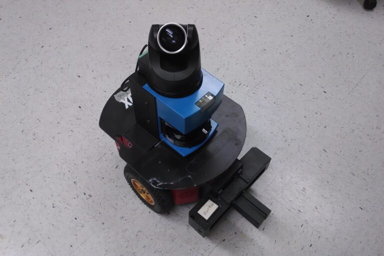
SLAM connects robot movement with environmental observations, while reliable navigation also requires tested localization and recovery. Photo: Tim36272 / Wikimedia Commons
Learn how SLAM builds robot maps, how localization differs from navigation, and how to test drift, loop closure, sensor timing and recovery in real environments.
SLAM stands for simultaneous localization and mapping. It lets a robot estimate its movement while building a representation of an environment that is not already fully mapped. The robot uses repeated observations to connect where it has traveled with the features it sees around it.
A convincing map is only part of a useful mobile robot. The system must also maintain a trustworthy position estimate, handle changes and recover when observations become ambiguous. This guide builds on our autonomy guide and explains how SLAM fits into a working navigation system.
Key Takeaways
SLAM estimates movement and builds a map together, while localization on an existing map, route planning and obstacle response are separate functions within the navigation system.
Reliable results depend on useful observations, calibrated sensor geometry and consistent timing, with repeatable environments and accumulated drift creating important failure cases.
Validate mapping and localization against independent physical checks, then test restarts, changed surroundings and recovery behavior before relying on the map for routine missions.
Why Mapping and Localization Depend on Each Other
To place a wall measurement on a map, the robot needs to know where its sensor was pointing. To work out where it is, it can compare current measurements with mapped walls. SLAM addresses these coupled estimation problems.
Imagine moving through an unfamiliar office while measuring corridors. Each new observation adds information, but small movement errors accumulate. Returning to a recognizable place gives the system evidence that earlier estimates need adjustment.
A map is therefore an estimated representation, not a perfect architectural survey. Its usefulness depends on the observations, motion, assumptions and required operating accuracy. A visually tidy result can still contain a scale error or a locally distorted area.
SLAM, Localization and Navigation
Mapping builds or updates a representation of the environment. Localization estimates the robot’s pose within a reference frame, often using an existing map. Navigation uses that estimate and other information to move toward a goal.
Pose includes position and orientation. For a planar mobile base, it is commonly expressed as horizontal position and heading. A drone or robot moving over complex terrain may need a fuller three-dimensional description.
Function
Main question
Example result
Odometry
How have I moved locally?
A short-term motion estimate from wheels, vision or other sensors
SLAM
Where have I moved, and how does the observed environment fit together?
A map and estimated trajectory
Localization
Where am I within an existing reference?
A position and orientation estimate on the map
Planning and control
How should I reach the goal?
A permitted path and movement commands
The Nav2 navigation concepts describe state estimation, environmental representation, planning and control as related components. SLAM does not automatically provide reliable docking, traffic coordination or a complete delivery workflow.
Our AMR guide covers those operational requirements. A robot can know its position and still have no usable route through a blocked aisle.
How a SLAM Pipeline Works
A typical system receives observations from lidar, cameras or other sensors and combines them with a motion estimate. It identifies relationships between observations, estimates the next pose and updates its map representation.
Many systems distinguish local estimation from a broader optimization stage. Local processing keeps up with incoming measurements. The broader stage uses relationships between places and observations to improve consistency over a longer trajectory.
Cartographer’s algorithm walkthrough illustrates this separation with local submaps and global constraints. It is one implementation of SLAM, rather than a description of every package’s internal architecture.
The practical implication is that a later correction may change the map or estimated historical trajectory. Treat map stability and localization behavior as engineering properties to test, especially when other software depends on coordinates remaining meaningful.
Lidar SLAM and Visual SLAM
Lidar SLAM uses range observations to align scans or point clouds. In an indoor planar application, a horizontal scanner may observe walls, columns and furniture. Three-dimensional systems can represent more of the scene’s geometry.
Visual SLAM estimates motion from camera observations. Monocular, stereo and RGB-D systems provide different kinds of information. Visual-inertial systems also incorporate an IMU. The ORB-SLAM3 paper demonstrates a research framework supporting several of these camera and inertial configurations.
No sensor choice is universally best. Cameras can depend on lighting and usable visual detail. Range measurements can be affected by visibility, target properties and limited geometry. Compare the environment and motion against the actual implementation’s assumptions.
A planar scanner is not a complete three-dimensional obstacle detector. Likewise, a detailed camera map does not prove that every relevant obstacle will be detected during motion. Select mapping and obstacle sensing around their separate requirements.
Our sensor guide explains the measurement and integration questions behind these choices.
Odometry, Drift and Loop Closure
Odometry estimates movement from a sequence of local measurements. Wheel rotation is one source, but wheel slip and imperfect geometry can introduce error. Visual or inertial estimates have their own uncertainties.
Drift is the accumulating difference between estimated and actual motion. A system may describe local movement smoothly while gradually misplacing a corridor or rotating its overall trajectory.
Loop closure occurs when the system recognizes that it has returned to a previously observed place and uses that relationship to constrain the estimate. It can reduce accumulated inconsistency. It also depends on recognizing the correct place.
Two similar aisles can create ambiguous evidence. A false association can distort the result instead of improving it. Include repeated structures and alternate return directions in testing rather than demonstrate only a distinctive room.
Do not assume every return to the start will repair all errors. The observations, matching criteria and optimization must provide a consistent explanation of the journey. Inspect both the local geometry and relationships across the entire mapped area.
Coordinate Frames and Sensor Timing
Measurements need a defined relationship to the robot. The system must know where each sensor is mounted and how its axes relate to the base. A small mounting error can affect many observations in the same direction.
Time matters because the robot moves while sensing. An image or laser scan belongs to an acquisition time, not simply the time a processing callback runs. Delayed data paired with the wrong pose can make stationary features appear inconsistent.
ROS conventions distinguish a locally continuous odometry frame from a map frame that can incorporate global corrections. The Nav2 state estimation documentation explains the map-to-odometry and odometry-to-base relationships.
Inspect those transforms and sensor timestamps before changing algorithm settings. Our ROS 2 guide covers the software concepts behind messages and coordinate transforms. Tuning cannot reliably compensate for a physically incorrect sensor model.
Maps, Costmaps and Moving Obstacles
A geometric map records environmental structure in a representation such as occupied grid cells or a point cloud. A navigation costmap assigns values used to evaluate movement, including obstacles and clearance around them.
Nav2’s costmap documentation describes layers that combine mapped information with sensor observations. The navigation representation can change as a person or pallet moves without requiring every observation to become permanent building geometry.
Keep semantic operating rules distinct as well. A passage may be physically open but prohibited for the robot, restricted by direction or available only during certain operations. Geometry alone cannot establish permission to enter.
A map can also become outdated. Moving a rack or rebuilding a partition may affect localization and routing differently. Define who approves changes, which maps and annotations belong together and how a verified version can be restored.
A Practical Mapping Workflow
Start by defining the operating area and the decision the map must support. A delivery robot needs useful routes and station references; a surveying task may require a different level of geometric accuracy and documentation.
Verify the inputs. Check sensor mounting, timestamps, units, motion estimates and frame relationships before collecting a large map.
Plan representative coverage. Include connecting corridors, turns and return paths, with visibility of stable environmental structure.
Collect controlled observations. Use an appropriate operating procedure and motion that the sensors and software can follow reliably.
Inspect the result. Look for duplicated walls, distorted intersections, inconsistent scale and areas built mainly from temporary objects.
Test localization separately. Reuse the saved map on independent runs rather than judge only the mapping session.
Version the approved configuration. Keep the map, sensor setup, parameters and operating annotations identifiable together.
Nav2’s setup guide discusses mapping with SLAM Toolbox and localization with AMCL. The supported packages and launch details depend on the chosen software distribution, so use documentation that matches the deployed version.
SLAM Toolbox also documents mapping modes and serialization options. A saved occupancy image and a serialized mapping state are different artifacts; record which one your intended workflow requires.
Measure Accuracy With Independent Checks
A map generated from the robot’s own estimates cannot independently prove those estimates correct. Compare important distances and positions with suitable external references, and state the uncertainty of those references.
For example, suppose a delivery mission needs to enter a staging zone within 100 millimeters of a specified reference. Test actual arrival position across repeated approaches and operating conditions. A map grid with 50-millimeter cells does not by itself prove 50-millimeter localization accuracy.
Separate the test targets. Global map consistency, pose accuracy, localization availability and docking repeatability answer different questions. Fine docking may use a local marker or dedicated sensing in addition to the facility map.
Record difficult runs as well as average performance. Report failed initialization, lost localization, recovery duration and operator intervention. A system that is usually accurate but occasionally selects the wrong aisle may be unsuitable despite a favorable mean error.
Test the Conditions That Break Assumptions
Include long repetitive corridors, low-detail areas, changed lighting where relevant, moving crowds and altered rack contents. The right cases depend on the sensor configuration and the site. Observe how the robot reports uncertainty rather than infer confidence from smooth motion.
Test startup from approved locations and recovery after a controlled loss of localization. Any physical relocation or disruption test should follow the supplier’s safe procedure. Specify who is allowed to reinitialize the pose and how they confirm it is correct.
Also test an unavailable destination and an outdated map version. The system should not silently treat every blocked or changed route as a localization problem. Logs should help distinguish perception, estimation, planning and mission-state failures.
Agree what the robot does when confidence is inadequate. Navigation capability does not replace independently validated protective behavior. A plausible pose estimate is not permission to move through an unsafe or prohibited situation.
From a Successful Map to a Maintainable System
Assign an owner for maps and configuration. Define when a layout change requires review, how updates are checked and how operators identify the approved version. Include backup and rollback in normal support procedures.
Budget for commissioning, calibration, computing, data storage and repeat testing. Open-source software can reduce some licensing costs, but it does not remove the work of building and maintaining the robot application.
Simulation can help investigate routes and sensing arrangements. Confirm important assumptions with the physical robot; our digital twins guide explains how model validation relates to the decision being made.
A useful SLAM deployment produces more than an impressive map. It provides repeatable localization, understandable failure behavior and a maintained connection between the robot’s model and the place where it operates.
Frequently Asked Questions
What does SLAM mean in robotics? It means simultaneous localization and mapping: estimating movement and building an environmental representation together using sensor observations.
Does a robot need SLAM for every mission? No. A robot may localize on a previously prepared map or use other positioning methods. Some workflows use SLAM during commissioning and a separate localization mode during routine operation.
Is obstacle avoidance the same as SLAM? No. Detecting and responding to nearby obstacles is separate from building a map and estimating pose. A robot can have local obstacle response without a globally consistent map.
Can SLAM work without GPS? Yes. Many indoor systems estimate movement from lidar, cameras, wheel data or inertial measurements. Their performance still depends on the environment and sensor configuration.
What is loop closure? It is the use of a recognized return to a previously observed place to constrain the estimated trajectory or map. Incorrect place associations can cause errors, so repeated-looking areas require testing.
How accurate is SLAM? There is no universal figure. Accuracy depends on sensors, calibration, motion, geometry and implementation. Measure the map and localization against independent references for the specific operating requirement.
Tesla confirms production-quality Optimus robots are leaving Fremont’s high-volume lines, but Musk says a 20,000-per-week pace remains at least a year away.