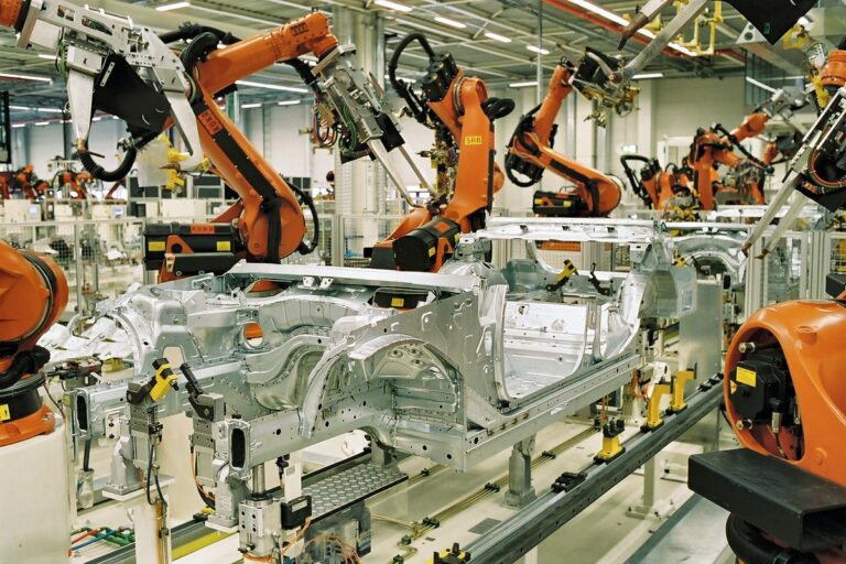
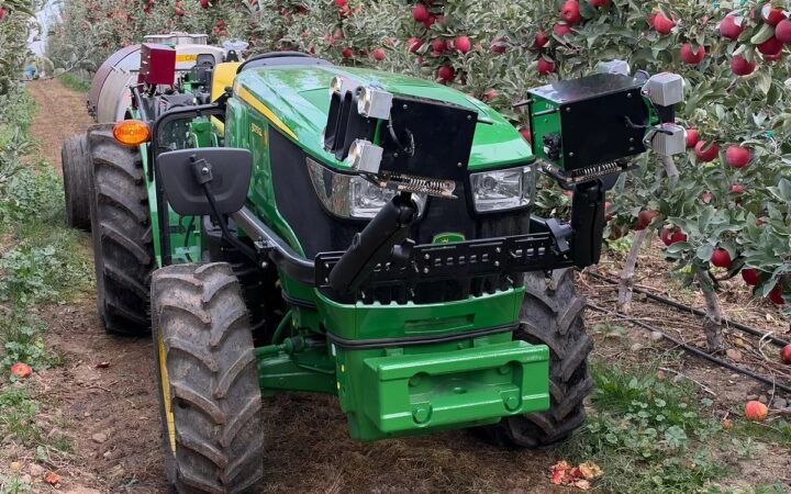
Offline robot programming prepares paths and task logic before controlled commissioning on the production machine. Photo: BMW Werk Leipzig / Wikimedia Commons
Offline Robot Programming: A Practical Guide From Simulation to Production
By Laura Bennett• 10 mins read
Published:
, Updated:
Learn how offline robot programming connects digital cell models, calibrated coordinates and controller code with practical commissioning and production handover.
Offline robot programming creates and checks a robot program in software before it is commissioned on the physical machine. Engineers can develop paths, examine access and prepare controller code while production continues or while a new cell is still being built.
The value comes from finding problems earlier and making commissioning more predictable. This guide continues our coverage of robot simulation and calibration, explaining how to move from a digital station to a controlled, verified production release.
Key Takeaways
Build the offline project around the actual robot, controller, tooling and measured station geometry, because a visually convincing model can still generate an unsuitable physical program.
Check the complete sequence, including joint configurations, approach and withdrawal paths, tool changes, station signals and recovery, rather than validating only the process path itself.
Treat generated code as a commissioning candidate that requires controlled physical verification, then keep the accepted robot program and its offline source synchronized through later changes.
What Offline Programming Does
Offline programming separates program development from occupying the production robot. The engineer describes the robot cell, defines tool motions and task logic, tests the intended sequence and prepares a program suitable for the target controller.
Different tools support different levels of fidelity. A geometric simulator can examine reach and interference. A controller-based environment can also reproduce aspects of the target controller’s program execution.
ABB’s developer documentation explains that RobotStudio’s virtual controller runs IRC5 or OmniCore controller software on a PC. It also explicitly identifies the continuing need for testing with a real robot system.
Offline programming is therefore part of an engineering workflow, with a defined boundary between what the software checks and what must be established on the installed machine.
Choose a Task That Benefits From Preparation
Applications with many path points, repeated product variants or expensive production interruptions can benefit from developing programs away from the cell. Examples include dispensing along a contour, following a welding seam or preparing several handling routines for related components.
A simple job may still be quicker to teach directly, especially when its geometry is poorly documented and few changes are expected. Compare total engineering effort, including model creation, measurement, debugging and commissioning.
Ask what the offline project needs to answer. An early layout study may only need credible access and reach checks. A production program needs more detailed geometry, controller behavior, tool definitions and process information.
Our ROI guide explains how to distinguish engineering convenience from a realizable operating benefit. Record the production time genuinely avoided and the work shifted into preparation.
Build the Station From Verified Inputs
Start with the correct robot variant, mounting arrangement and controller configuration. Similar-looking robots can have different reaches, joint limits or supported options. Include external axes and their relationship to the robot where the application uses them.
Add fixtures, parts, fences, tool stands and nearby equipment that affect movement. Represent the tool in enough detail to examine clearance around its body, adapters and other protrusions.
Keep a register of assumptions. A fixture position taken from an early layout drawing should remain distinguishable from a measured installed position. Resolve the assumptions that affect the next engineering decision before treating the model as authoritative.
Project input
What to verify
Why it matters
Robot and controller
Variant, software and installed options
Available motion and program behavior
Tool
Geometry, tool center point and loading data
Path accuracy and clearance
Workstation
Fixture location and actual obstacles
Reach and physical interference
Interfaces
Signals, acknowledgments and timeouts
Sequence execution and recovery
A detailed model is useful only when its relevant dimensions and relationships are trustworthy. Preserve enough geometry for the checks being performed rather than spend effort on purely decorative detail.
Establish Tool and Workpiece Coordinates
The tool center point, or TCP, defines the working point of the tool relative to the robot flange. A workpiece reference frame defines where the part or fixture sits relative to the robot.
Both relationships connect the digital path with the physical task. A correct contour attached to the wrong workpiece frame can become a consistently misplaced path. An incorrect TCP can also create errors that change with tool orientation.
RoboDK’s setup documentation includes procedures for defining tools and reference frames. Use the supported measurement and calibration procedure for the selected system, then verify the result at representative locations and orientations.
Distinguish repeatability from absolute accuracy. Repeatedly returning to the same taught position does not establish that a robot will accurately reach every position calculated from CAD. Determine the accuracy the process actually requires and validate it across the working area.
Plan Complete Motions, Not Just Target Points
A target describes a desired pose. The path between targets determines how the robot gets there. Specify approach, process and withdrawal motions, including the space needed when a tool or object is carried.
Review joint configurations as well as the tool path. A robot may reach the same tool pose through different arm arrangements, with different consequences for clearance and subsequent movement.
Check transitions between routines. A process path can look correct while the move from the preceding routine takes an unexpected route. Include startup, parking and travel to tool stands in the same review.
Our motion-planning guide explains paths, trajectories and execution. For offline work, retain the intended speed, acceleration and blending settings alongside the targets so the program’s meaning survives transfer.
Understand What Collision Checks Can Establish
A collision check evaluates the geometry and checking settings supplied to the software. Missing clamps, simplified tooling or an incorrectly located fixture can make the result misleading.
Check which object pairs are included, how moving equipment is represented and whether the carried part follows the robot correctly. Examine narrow clearances and transitions rather than accepting a green status without reviewing its scope.
Do not treat a small modeled gap as proof of adequate real clearance. Manufacturing tolerances, measurement error, tool deflection and unmodeled items can consume that gap. Establish margins through the application’s engineering process and verify them physically.
Collision-free task planning also does not establish a safe installation. Protective measures and application validation remain separate responsibilities, as described in our safety guide.
Include Signals and Process Equipment
Real robot tasks depend on events outside the arm. A clamp must be confirmed closed, a machine must be ready and a receiving station must accept the next part.
Define the meaning of each request, acknowledgment and completion signal. A command to close a gripper is different from evidence that the intended part is held. A simulated attachment event may illustrate possession without reproducing the physical grasp.
Model the states needed to test sequence behavior, then document what remains represented by assumptions. Include missing responses, unavailable stations and timeouts in the test plan.
The integration guide provides a foundation for these interfaces. Keep the robot sequence, PLC logic and equipment behavior aligned so each system agrees when work may proceed.
Generate Code for the Actual Controller
Some environments develop directly against a vendor’s virtual controller. Others translate a common program representation into controller-specific instructions.
RoboDK calls that translation a post processor. Its documentation distinguishes program generation from a robot driver used for real-time communication. Selecting a robot model alone should not be treated as confirmation that every controller feature is supported.
Verify the intended controller generation, software options, file conventions and supported instructions. Check how the output represents tools, work frames, motion settings, subprograms and input/output operations.
Inspect the generated program and any warnings before transfer. Record the post-processor version and configuration with the project so an export can be reproduced and investigated later.
Estimate Cycle Time With Explicit Assumptions
A useful estimate includes motion, process time, equipment response and waiting. Running a simulation faster changes how quickly the engineer watches it; it does not make the production robot faster.
For an illustrative sequential task, assume 18 seconds of robot movement, 10 seconds of process work, six seconds of fixture actions and four seconds of required confirmation. The complete assumed cycle is 38 seconds, corresponding to a theoretical maximum of about 94.7 cycles per hour.
If testing reveals another seven seconds of station waiting, the cycle becomes 45 seconds and the theoretical maximum falls to 80 cycles per hour. Both figures exclude breaks, faults, changeovers and other losses; they are scenario calculations rather than production forecasts.
Compare estimates with measured complete cycles and investigate the difference by stage. A faster arm path may have little effect when a machine or fixture remains the limiting resource.
Commission the Program Through Controlled Checks
Prepare a reviewable release package before transferring code: intended robot, program revision, tool and frame data, required equipment state and the commissioning plan.
Qualified personnel should verify the installed configuration and follow the manufacturer’s and site’s approved procedures. Initial movement checks, process trials and testing at the intended operating conditions are distinct steps, each requiring the appropriate controls.
Check representative targets, approach directions and clearances against the actual station. Verify signal meanings with the connected equipment and confirm that the process produces acceptable results.
Record discrepancies and correct the responsible source. If a fixture frame is wrong, identify that cause before individually shifting many targets. Otherwise, local edits can conceal a systematic problem and make future product changes harder.
Test Interruptions Before Handover
A normal cycle is only one operating condition. Define what happens when a part is absent, a station refuses a request or the sequence is interrupted while the robot holds an object.
Recovery needs a known physical state. “Restart the program” is incomplete if the gripper may already contain a part or the machine may have accepted the previous one.
Use approved test procedures to establish when work can resume, when an operator must inspect the cell and which state must be reconciled first. Avoid creating hazardous conditions merely to demonstrate a fault response.
Keep the accepted recovery behavior with the production program and operator documentation. This makes the handover useful to the people who will maintain the installation after commissioning.
Keep the Offline Source and Robot in Agreement
Once production begins, a controller edit can leave the offline project out of date. A later export may then overwrite an important correction or reintroduce a problem that was already resolved.
Define how changes are captured, reviewed and incorporated into the master project. Store the accepted generated program, source station, tool and frame data, controller configuration and validation records together.
Recheck the affected behavior after a tool replacement, fixture move or software change. Our maintenance guide explains why configuration records and change history matter to dependable operation.
Offline programming works best as a maintained engineering process: prepare the task, expose assumptions, verify the physical result and preserve what was accepted. That discipline makes the next product or process change easier to understand and qualify.
Frequently Asked Questions
What is offline robot programming?
It is the development and checking of robot programs in software away from the physical production robot, followed by transfer and controlled commissioning on the intended machine.
Is offline programming the same as simulation?
Simulation examines modeled behavior. Offline programming also prepares executable robot programs; a simulation used only for layout planning may not generate controller code.
Does it eliminate teaching on the real robot?
It can reduce work performed at the cell, but physical checks, calibration and process adjustments may still be necessary. The amount depends on model accuracy, tooling and the application.
What is a post processor?
It translates an offline program into instructions for a particular robot controller. Its supported features and configuration need to match the intended production system.
Can a collision-free simulation be run immediately?
The result applies to the supplied model and checking settings. Verify the installed equipment, coordinates, generated program and application through an approved commissioning process.
What should be saved after commissioning?
Keep the accepted controller program, offline source, tool and frame data, relevant software versions, interface definitions and validation records, with a defined process for later changes.
XPENG will demonstrate its latest IRON humanoid at AI Day in Guangzhou on November 25, putting on-device physical AI alongside robotaxi and mobility updates.