Learn how robot actuators combine motors, gearing, feedback and control, with practical load calculations and tests for speed, heat and repeated operation.
Robot actuators turn supplied energy into controlled movement. A joint actuator may combine a motor, transmission, feedback devices, brake and electronics. Its useful capability depends on how those elements work together throughout the required motion.
Choosing an actuator therefore means more than comparing peak torque. This guide builds on our robot arm guide and explains how load, speed, gearing, feedback and heat determine what a robot can repeatedly deliver.
Key Takeaways
Size an actuator around the complete motion and load profile, including gravity, acceleration, process forces and the time available for cooling between demanding movements.
A gearbox exchanges speed for torque while introducing efficiency, stiffness and transmission limits, so output performance cannot be inferred from motor torque alone.
Evaluate the assembled drive with suitable feedback and the real duty cycle, then verify positioning, thermal behavior, load holding and fault response before release.
The Actuator Is a Complete Drive Chain
The motor produces mechanical effort. A transmission adapts that effort to the joint or linear axis. Feedback reports motion or state, while drive electronics regulate electrical power. The robot controller coordinates the resulting movement with the rest of the mechanism.
These components have separate limits. A motor may tolerate a short peak that exceeds the gearbox’s permitted load. A suitable mechanical assembly may still be constrained by the drive’s current capacity or available supply voltage.
Identify the boundary of the product being compared. An integrated joint module and a bare motor are not equivalent offers. Ask which bearings, brakes, sensors, electronics and protective functions are included and what the machine builder must provide.
Electric, Pneumatic and Hydraulic Actuation
Actuation family
Useful characteristics
System questions
Electric
Controllable rotary or linear motion with many feedback and transmission options
Are torque, speed, heat removal and electrical supply suitable for the full cycle?
Pneumatic
Simple repeated movements and gripping where compressed air is available
How do air quality, pressure variation, compliance and consumption affect the task?
Hydraulic
High-force applications with an appropriate fluid-power system
How are power supply, leakage, temperature, control and service managed?
No family is universally best. A two-position gripper and a continuously controlled robot shoulder impose different requirements. Compare the whole installation, including pumps, compressors, valves, wiring and maintenance, rather than only the device attached to the joint.
For this guide, the remaining examples focus on electric robot drives. The same requirement-first approach applies elsewhere: define movement, load and acceptable behavior before selecting hardware.
Servo Describes Control, Not One Motor Shape
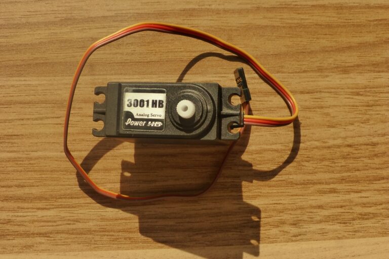
A servo system uses feedback to regulate a quantity such as position, velocity or torque. Different motor technologies can participate in that architecture. A small hobby servo and an industrial robot joint share a general feedback concept but have very different interfaces and capabilities.
Brushed motors use mechanical commutation, while brushless drives use electronic commutation. Stepper motors are designed for incremental electromagnetic motion and can be used with or without feedback. “Stepper” and “closed loop” are not mutually exclusive descriptions.
FAULHABER’s stepper note explains the operating principle. Evaluate the selected drive’s speed-dependent torque, feedback and load behavior instead of assuming that commanded steps always equal achieved movement.
Our sensor guide explains the distinction between measuring the motor and measuring the output mechanism. The appropriate arrangement depends on the accuracy and diagnostic requirements.
Start With the Load and Motion Profile
Describe position, speed and acceleration over the cycle. Identify the time spent accelerating, moving steadily, decelerating and holding. Include changes in load, tool orientation and process contact.
Gravity can dominate an arm joint even when it moves slowly. As an illustrative calculation, an 8 kg load acting at a horizontal distance of 0.4 meters produces about 31.4 newton-meters of gravitational moment. That excludes the arm’s own mass, tooling and dynamic effects.
Acceleration adds another requirement. A long load may have substantial rotational inertia even when its mass seems modest. The joint must also overcome relevant friction and any force imposed by the process.
Use a documented mechanical model and supplier review for final sizing. Do not apply a single arbitrary safety factor to a guessed load and treat the result as a validated design. Uncertainty and consequences need explicit consideration.
Torque and Speed Belong Together
An actuator has an operating envelope rather than one universal torque number. The available effort can depend on speed, supply, temperature and the permitted duration. A quoted maximum may describe a short event rather than routine service.
Mechanical power is related to torque and angular speed. Asking for more of both increases the required power; a gearbox cannot create energy. Supply and drive constraints therefore matter alongside the mechanical rating.
Maxon’s technical information distinguishes continuous operating limits from other motor data. Check the conditions behind the selected product’s ratings, especially the assumed mounting and heat removal.
Stall torque is not a continuous operating recommendation. Holding a loaded axis can generate heat without useful output motion. Establish how the joint supports the load during dwell and what happens when drive power is unavailable.
What a Gearbox Changes
A reduction gearbox lowers output speed and increases available output torque, subject to losses and the transmission’s own ratings. It also affects reflected inertia, stiffness, friction and the ease of moving the output from the load side.
For an illustrative steady-state calculation, a motor producing 0.3 newton-meters through an 80:1 reduction at 85% efficiency would deliver about 20.4 newton-meters. A motor speed of 3,000 rpm would correspond to 37.5 rpm at the output.
Those figures do not establish allowable continuous service. The actual gearhead must tolerate the torque, speed, duty and loads, and efficiency can vary with operating conditions. Include bearings and external moments in the review.
Maxon’s gearhead overview includes several transmission families. Harmonic Drive’s strain-wave explanation describes a compact mechanism using a wave generator and flexible spline. Select a transmission by application requirements rather than its name alone.
Backlash, Compliance and Backdrivability
Backlash describes lost motion associated with clearance when movement reverses. Compliance describes deflection under load. A low-backlash transmission can still deflect, and a stiff mechanism can still have other positioning errors.
These effects influence contact tasks and reversals. A motor encoder may report the expected angle while the output moves differently because of transmission behavior. Test the relevant load and direction changes at the process.
Backdrivability concerns whether an external load can move the mechanism through the transmission. It can affect manual interaction and force control, but should not be inferred solely from gear ratio.
Do not assume that friction or a high reduction ratio provides a safe holding function. Where load retention is required, use an engineered arrangement with the appropriate documented capability.
Linear Actuators and Transmission Choice
Many robot mechanisms need translation rather than rotation. A motor can drive a screw, belt or other transmission, while some actuators generate linear motion directly. Compare the complete axis, including guides and the structure that carries external loads.
For a screw-driven axis, lead connects rotational speed with travel speed. The same choice affects the relationship between motor torque and thrust, subject to efficiency and load limits. A useful selection considers required stroke, acceleration, positioning and service conditions together.
Side loads and moments may need dedicated guidance rather than being carried by the actuator’s moving rod. Also check the axis behavior at both ends of travel and under the intended mounting orientation.
As with rotary gearing, do not infer load holding from the transmission type. The exact screw, friction, brake and load arrangement determine behavior. Ask for documented limits and verify the assembled axis through the approved acceptance process.
Feedback and Control Loops
A drive may use nested control loops for current, velocity and position. Feedback quality, sampling, filtering and mechanical behavior affect the result. An aggressive setting that works without a load can behave poorly with a flexible tool.
Motor current can inform torque estimation under defined motor and control conditions. It does not automatically measure contact force at the tool, especially through frictional transmissions and a moving multi-joint mechanism.
Maxon’s feedback guidance discusses how sensing and mechanical connections influence control. Keep units, encoder configuration and the relationship between motor and output coordinates explicit.
Our calibration guide explains why correctly controlled joint motion still needs a valid relationship to physical tool and workpiece coordinates.
Thermal Behavior and the Repeated Cycle
A short demonstration can hide a thermal limitation. Repeated accelerations and long holding periods may gradually raise temperature until the drive reduces output or the system stops.
Describe the actual duty cycle and ambient conditions. Include the installed enclosure, available cooling and nearby heat sources. A motor tested on a favorable heat sink may not behave the same way inside a compact robot joint.
Ask the supplier to evaluate both short peaks and repeated loading. The complete torque history is more informative than the largest isolated value. Also check whether temperature monitoring represents the component that limits operation.
Run representative endurance trials long enough to assess stable behavior, following the equipment’s approved procedures. Record temperatures, performance changes and any protective limiting alongside the production output.
From Component Selection to Acceptance
Create a requirement sheet covering load, motion, working environment, feedback, holding behavior and service access. Document the assumptions used to choose the motor, transmission, drive and power supply.
Movement: Verify required travel, speed and settling with representative tooling and load.
Process: Measure useful positioning or force outcomes at the actual task.
Endurance: Check the repeated duty cycle and thermal behavior rather than one peak movement.
Recovery: Verify approved responses to unavailable power, feedback faults and interrupted motion.
Connect the accepted drive limits to the motion configuration. Our planning guide explains why a geometric path needs suitable timing and execution constraints.
Finally, establish inspection and replacement arrangements through the maintenance plan. The best actuator choice delivers the required movement repeatedly and leaves the operating team with understandable limits and service procedures.
Frequently Asked Questions
What is a robot actuator? It is a device or assembly that turns supplied energy into movement. A joint module can include a motor, transmission, feedback, brake and drive electronics.
Is a servo motor different from a brushless motor? The terms describe different aspects. Brushless refers to motor construction and commutation, while servo describes a feedback-control arrangement.
Does a larger gearbox ratio always improve a robot? No. Reduction trades speed for torque and changes losses, stiffness and other behavior. Select the ratio around the complete movement and transmission ratings.
Can peak torque be used continuously? Only if the manufacturer explicitly permits the operating condition. Short-duration peaks and stall figures should not be treated as continuous ratings.
Does an encoder prove the tool reached its target? Not by itself. Transmission behavior, calibration, fixture position and the measurement location affect the relationship between encoder data and the physical process.
What should an actuator trial include? Representative load and motion, repeated operation, process accuracy, thermal behavior and approved fault recovery. Test the assembled drive rather than only the bare motor.