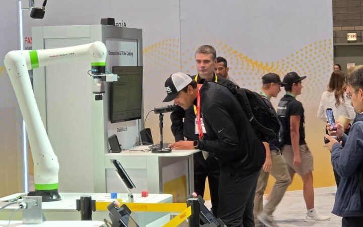
Force control connects measured interaction with robot motion to support consistent contact and independently verified process quality. Photo: David Baillot / UC San Diego Jacobs School of Engineering
Understand robot force control, impedance and compliance, then plan sensing, contact behavior and validation around reliable physical results.
Force control lets a robot regulate how it interacts with a surface or object rather than rely only on a prescribed position. It can support operations such as inserting a part, following a surface or maintaining contact during finishing, provided the tooling, sensing and control are suitable for the task.
The challenge is the complete interaction: approaching, making contact, performing useful work and leaving without an ambiguous result. This guide extends our sensor guide and explains how force control, compliance and physical validation fit together.
Key Takeaways
Define the physical contact result and controlled directions before selecting a force-control method, because position, force and compliance describe different requirements.
Interpret force measurements through the tool, payload, reference frame and motion conditions, separating intended process contact from gravity, acceleration and installation effects.
Validate approach, contact, process quality and recovery with representative parts, while keeping ordinary force regulation separate from protective functions for people.
Why Position Control Alone Can Be Insufficient
A position command asks the robot to reach or follow a pose. If the actual surface is slightly displaced from its model, that request may produce unexpected contact or leave the tool short of the work.
A compliant interaction allows some motion in response to loading. That can accommodate limited variation, but the required behavior depends on the process. Inserting a component, wiping a surface and grinding an edge do not share one universal control setting.
MIT’s control notes discuss the distinction between trajectory tracking and contact-force reasoning. The application still needs a definition of success beyond the controller’s immediate target.
Start with the part tolerance, allowable loading, contact geometry and required finished quality. Force control should address a demonstrated process requirement rather than compensate for every poorly located fixture.
Force, Impedance and Admittance
Concept
Main idea
Question for the application
Position control
Track a specified pose or movement
What happens when the surface differs from the assumed geometry?
Force regulation
Use an appropriate controller to pursue a desired interaction load
How are contact, loss of contact and force limits handled?
Impedance control
Shape the relationship between motion and interaction effort
What effective stiffness and damping suit the mechanism and task?
Admittance control
Use measured effort to generate a motion response
Are sensing, timing and the underlying motion controller compatible?
Names can describe different implementations across products. Ask which quantities are measured, which are commanded and which limits remain active. A feature called “compliance” does not completely specify its behavior.
Research on variable impedance studies motion generation with changing stiffness and damping. For an installation, those concepts require a controller and validation appropriate to the actual robot, contact and tooling.
Select the Controlled Directions
A process can combine different requirements along different axes. A surface-following tool may regulate contact normal to the surface while following a planned route tangentially. An insertion may need a different combination of translational and rotational behavior.
Choose a reference frame that makes these directions meaningful. “Push along Z” is incomplete unless everyone knows whether Z belongs to the tool, robot base or another task frame.
Universal Robots’ force documentation describes configurable compliant axes and reference features. Follow the specific product’s supported modes instead of transferring a parameter set from another controller.
Our calibration guide explains how tool and workpiece frames relate to the physical installation. A correct force value expressed in the wrong frame can produce the wrong interaction.
What the Force Sensor Measures
A six-axis transducer reports force and moment components at its measurement interface. The readings can contain tool weight, movement-related effects and process contact. They are not automatically a direct measurement of only the force at the desired contact point.
ATI’s sensor FAQ discusses force/torque measurement and system considerations. Select range, overload capability, resolution and interface behavior for the complete load, not just the small contact force of interest.
Mounting geometry matters. A contact away from the measurement origin can produce a moment as well as a force. Keep the tool geometry and coordinate transformation documented when interpreting those components.
A robot may also estimate interaction effort from joint measurements and a model. Determine what the product actually provides and which uncertainties affect it. Do not treat an estimate and a dedicated external measurement as interchangeable without evidence.
Check Range and Measurement Quality
Resolution, accuracy and overload capacity answer different questions. A small displayed increment does not establish that the absolute contact estimate is accurate, and a sensor capable of surviving a large load may still be unsuitable for measuring a much smaller process signal.
Define how the application identifies a measurement outside the accepted range, an unavailable sample or a changed zero reference. Saturated or invalid data should not be presented to the controller as a trustworthy process measurement.
Include installation effects in the checks. Cable loading, mounting changes and temperature can influence the measurement or its interpretation. Compare unloaded readings and a suitable independent reference under documented conditions before diagnosing every change as a contact problem.
Payload, Zeroing and Compensation
Tool mass and center of gravity affect measured loading as the wrist changes orientation. Acceleration adds further effects. A useful setup needs the appropriate payload model and compensation supported by the equipment.
For an illustrative scale comparison, a 3 kg tool has a gravitational force of about 29.4 newtons. A process seeking a much smaller contact force therefore depends on distinguishing the tool’s contribution from the interaction.
Zeroing at one pose does not necessarily remove orientation-dependent effects everywhere. Zeroing while an unintended contact load is present can also hide that load in the reference.
Use the supplier’s approved setup procedure and independently check behavior across the relevant orientations. Record the conditions and tool assembly used, so a later tool change does not silently invalidate the interpretation.
Compliance Is a Measurable Relationship
In a simple static linear model, force is proportional to displacement through stiffness. An illustrative stiffness of 2 newtons per millimeter and a 0.5-millimeter displacement correspond to a 1-newton change. This explains units and relationships; it is not a recommended controller setting.
Real contact also involves damping, inertia, friction and geometry. Lower stiffness does not automatically make a task stable or accurate, and a more rigid response is not automatically better.
Rotational behavior uses different quantities and units from translation. Ensure that the engineering record distinguishes forces from moments and linear displacement from rotation.
Mechanical compliance can be useful as well. A suitable alignment device or tool interface may accommodate a defined mismatch without requiring the controller to infer every detail. Compare mechanical, sensing and control options against the same process requirement.
Approach, Contact and Loss of Contact
A force controller operates differently before and after contact. If the requested interaction is absent, the system may move while seeking it, depending on the implementation. The application needs bounded, documented behavior for that phase.
Define the permitted approach region, motion conditions and expected contact evidence through the approved design process. Include a missing workpiece or misplaced surface in the test plan.
Specify what happens when contact disappears during the operation. A tool leaving an edge or encountering a gap should not produce an undefined continuation. Time, motion and process-result checks may all be relevant.
Our planning guide covers movement constraints. Contact control belongs within that wider application rather than being treated as a replacement for every motion limit.
Timing and Filtering Affect the Interaction
Measurements, processing and motion response take time. Filtering can reduce noise but also change how quickly the system reacts. Mechanical flexibility and contact stiffness influence the resulting behavior.
Do not choose gains by copying a demonstration or maximizing a response setting. Use the controller manufacturer’s guidance and qualified application engineering for the exact hardware and process.
Inspect time-aligned records of requested and measured effort, robot motion and task state where available. A smooth average trace can conceal short peaks or repeated loss of contact.
Keep units and timestamps consistent across recording systems. If a quality event is logged on another controller, establish how its timing relates to the force and motion data before drawing a causal conclusion.
Validate the Process, Not Only the Force Trace
A correct average force can accompany a poor finished result. A part may be only partly seated, a surface may be inconsistently finished or a tool may contact the wrong feature.
For a hypothetical insertion task, define success using the actual seating and quality requirement, then record loading, completion time and interventions. Include representative tolerances and challenging legitimate parts.
Test entry, steady interaction, exit and interrupted recovery. A trial that begins with the tool already in ideal contact omits an important part of the application.
Our integration guide explains why completion signals must represent physical results. A controller exiting force mode is not sufficient proof that the workpiece is acceptable.
Safety and Fault Handling
Ordinary force regulation should not be assumed to provide validated protection for people. Tool shape, trapping points, process hazards and the complete moving system remain relevant.
Use the application assessment and protective architecture described in our safety guide. Do not infer permissible human contact from a process-force target.
Define approved responses to unavailable sensing, invalid data, communication loss and unexpected contact. The response should establish a known state rather than silently continue using stale measurements.
Keep the operator’s recovery duties clear. Resolving an uncertain part or contact condition may require an approved intervention instead of automatically repeating the force-controlled motion.
Maintain the Accepted Setup
Save the controller mode, reference frame, tool model, sensor configuration and validated operating limits together. Record the physical tooling and test conditions behind acceptance.
Review affected behavior after sensor replacement, tool wear, changed part material, altered fixtures or controller updates. A mechanically different tool can change the interaction even when the program is unchanged.
Our maintenance guide connects inspection and fault evidence to reliable recovery. Trend process quality and interventions alongside force data rather than rely on one signal alone.
A useful force-controlled application has a defined contact objective, bounded behavior and independently verified output. The value comes from consistent physical work, not merely enabling a controller feature.
Frequently Asked Questions
What is force control in robotics? It is control that accounts for or regulates interaction effort rather than relying only on a prescribed pose. The exact sensing, command and compliance behavior depends on the implementation.
Are impedance and admittance control identical? No. They describe different ways of relating effort and motion. Product implementations and interfaces vary, so determine which quantities are measured and commanded.
Does a force sensor measure only contact force? No. Tool weight, motion and mounting geometry can contribute to the reading. Appropriate modeling, compensation and interpretation are required.
Can force control fix inaccurate fixtures? It can accommodate some defined variation in suitable applications, but it does not remove the need for appropriate fixturing, calibration and bounded motion.
Does a low force setting make a robot safe around people? No. Process-force regulation is not a substitute for an application assessment and validated protective functions.
What should a force-control trial prove? It should verify approach, contact, process quality, exit and recovery with representative parts and conditions, including missing or interrupted contact.