Learn how to plan robot machine tending for CNC equipment, from part presentation and workholding to cycle time, inspection and dependable unattended operation.
Robot machine tending automates the loading and unloading of production equipment, including CNC lathes and machining centers. Its value comes from keeping a proven process supplied with correctly located workpieces and removing finished parts reliably.
The robot is only one part of that system. Workholding, part presentation, machine interfaces, inspection and recovery determine whether a cell produces acceptable parts for a useful operating period. This guide develops the deployment principles in our automation guide into a practical CNC application.
Key Takeaways
Choose a repeatable part family and a stable machining process before automating loading, then evaluate the complete cell against good-part output and required operator attention.
Design part presentation, gripping, seating checks and machine handshakes together, accounting for chips, coolant, changing part geometry and interrupted sequences.
Validate a realistic unattended operating window through input capacity, tool life, inspection, output storage and tested recovery, rather than assuming a fast robot creates continuous production.
What Machine Tending Includes
A basic cycle takes a blank from an input location, places it in the machine, allows processing, removes the finished part and deposits it at an output location. More demanding applications add reorientation, a second operation, cleaning, gauging or routing of rejected parts.
The CNC machine still performs the cutting process. The tending system handles the material and coordinates permission to perform each stage.
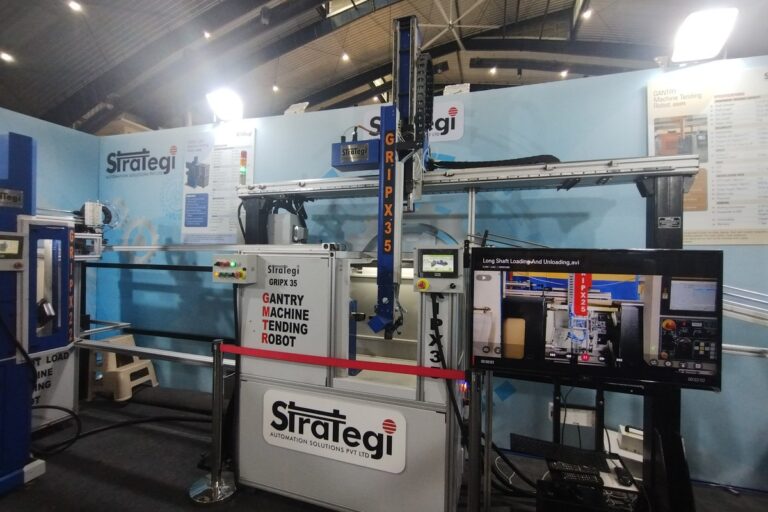
Articulated arms are one option. Cartesian or gantry loaders, dedicated automatic part loaders, bar feeders and pallet systems may suit particular machines and part families. Select an architecture from the task rather than from the appearance of a robot demonstration.
Our robot arm guide explains payload and workspace trade-offs. A constrained, repeatable loading task can favor a different mechanism from a cell that must reorient diverse parts.
Choose the First Part Family
Start with a documented part family: material, blank dimensions, finished geometry, batch sizes and required operations. Identify the variations the cell must handle automatically and those that require a planned changeover.
A stable cutting process matters. Automation does not correct an unpredictable machining cycle, frequent tool breakage or inconsistent stock that prevents reliable loading.
Measure the current process before estimating improvement. Record machine cutting time, door and workholding time, loading effort, inspection, interruptions, scrap and waiting for an operator.
A favorable first application often has dependable workholding, manageable part presentation and enough repeat demand to justify engineering. High volume is useful only if acceptable parts can be produced consistently.
Define the Complete Production Cycle
Stage
Physical requirement
Evidence to define
Pick a blank
Correct part and orientation available
Part identity and successful grasp
Load the machine
Part located against the intended references
Seating and workholding confirmation
Run machining
Machine permitted to process the assigned job
Robot clear and machine completion state
Unload and inspect
Finished part removed and handled appropriately
Part location, quality disposition and traceability
Recover
Interrupted material and equipment state resolved
Approved restart point and accountable operator action
Write these requirements before programming movement. A sequence of robot poses does not establish that the correct blank was loaded or that the finished work passed inspection.
Our integration guide explains task ownership and acknowledgments. Every handoff should represent a defined physical condition, not merely the last command issued.
Make Part Presentation Repeatable
Trays, drawers, conveyors and bins create different engineering demands. A tray can provide known pickup locations but requires controlled replenishment; unstructured bin picking adds perception, reachability and grasp-selection requirements.
Account for the actual incoming stock. Burrs, oil, sticking parts and dimensional variation can affect separation and pickup. A clean sample arranged for a demonstration is not representative of every production batch.
Distinguish raw and finished surfaces. A grip that is acceptable on a blank may mark a machined feature or fail after the geometry changes.
Where vision is needed, use the principles in our machine vision guide. Specify what the camera must establish, then verify it across the lighting, contamination and part variations the cell will encounter.
Select the Gripper for Both Directions
Include the tool, adapters, cables and every simultaneously held part in the robot payload assessment. A dual gripper may carry a raw blank and a finished part at the same time.
Haas’s robot operation manual explicitly distinguishes gripper mass, raw-stock mass and finished-part mass. Its setup also treats raw and finished gripping separately, illustrating why a single part-weight figure is incomplete.
Consider the surfaces available for gripping, expected coolant exposure, chips, part temperature and access inside the enclosure. Determine how the application detects an unsuccessful grasp and retains or resolves the part after an interruption.
Our gripper guide covers selection and validation. Test the full handling route with representative parts rather than accept a stationary grip as proof of dependable tending.
Workholding and Seating Need Separate Attention
The robot must deliver the workpiece to the intended locating surfaces without leaving it tilted, short of position or trapped against contamination. A fixture closing does not automatically establish correct seating.
Define suitable evidence for part location and clamp state with the machine and fixture suppliers. These may be separate checks with different purposes; their implementation depends on the equipment and application.
Haas’s loader manual documents distinct pickup, loading, alignment and unloading stages. It also provides dedicated recovery behavior for interrupted cycles, reinforcing the need to manage more than a pickup and drop-off pair.
Inspect the effect of chips and coolant over repeated cycles. A process that seats correctly with a freshly cleaned fixture may behave differently after hours of cutting.
Check the Entire Workspace
Reach means more than touching the chuck or vise. The loaded tool needs a feasible approach, clearance from the door and machine structure, and room to leave without collision.
Consider the machine’s internal axes, fixtures and tools in the loading configuration. The geometry can change between jobs even if the robot base remains fixed.
Our calibration guide explains the relationship between programmed frames and physical tooling. Record the accepted tool and machine references as part of each configuration.
Use simulation where it helps check access and layout, then validate the physical installation through approved commissioning. Cable routing, compliance, part variation and uncertain states require attention beyond a nominal collision-free model.
Design the Machine Interface
Define the permitted states for loading, machining and unloading with the equipment suppliers. The design needs appropriate coordination of the door, machine axes, spindle, workholding and robot position.
Ordinary production signals and protective functions serve different purposes. A general “ready” bit must not be treated as proof that all required safety conditions are satisfied.
Keep the job identifier and part state visible. After a network interruption, neither controller should silently assume that the other completed an operation when the physical state is uncertain.
Document responses to missing confirmations and timeouts. Use supported machine interfaces and approved integration; bypassing an interlock or substituting a fixed delay for necessary state evidence is not a valid way to make the sequence reliable.
Calculate Cycle Time Without Overstating the Gain
Suppose a hypothetical machine cuts for three minutes and needs 45 seconds of nonoverlapping manual handling. The nominal cycle is 3.75 minutes, equivalent to 16 parts an hour before losses.
If robot tending reduces that handling interval to 30 seconds, the corresponding cycle is 3.5 minutes, or about 17.1 parts an hour. The nominal increase is about 7.1%, not a doubling of machining capacity.
Automation can still create significant value by reducing waiting, improving consistency or enabling additional operating hours. Those benefits must be measured separately rather than attributed entirely to faster handling.
Our ROI guide shows how to connect installed cost with realizable benefits. Compare good output, operator requirements and quality losses over the actual production schedule.
Define an Unattended Operating Window
An input tray is only one limit on unattended operation. Finished-part storage, tool life, chip accumulation, coolant condition and required inspection may end the run earlier.
Using the hypothetical 3.5-minute cycle, 40 available blanks support at most 140 minutes of nominal production from an empty machine. That upper bound assumes no interruptions and adequate capacity everywhere else.
Define what happens when an inspection fails, a tool limit is reached or output storage fills. The system needs an appropriate stop or escalation rather than continuing because more blanks remain.
Specify who receives alerts and how quickly qualified support is available. A notification alone does not restore production, and a remotely visible camera does not resolve an uncertain fixture or part condition.
Consider Shared Robots and Changeovers
One robot serving multiple machines can improve equipment utilization, but it also introduces scheduling constraints. A robot occupied at one machine may leave another waiting, especially when cycle completion times coincide.
Model the full service time, including travel, door operations and part exchanges. High robot utilization can leave little capacity for variation or recovery.
For mixed production, define a controlled recipe containing the machining program, fixture, gripper, part presentation, frames and inspection requirements. Changing a robot program alone is not a complete changeover.
Measure the first acceptable part and total changeover effort. A flexible system is useful when its setup can be performed correctly and economically by the people who will operate it.
Qualify Quality, Recovery and Sustained Output
Establish acceptance criteria before the final demonstration. Include dimensional and surface quality, complete-cycle success, intervention rate, actual output and the duration the cell must run.
Use representative stock and normal operating conditions. Include planned, approved tests of missing material, rejected parts, interrupted cycles and an unavailable downstream position.
Recovery should reconcile the actual part and machine state before restarting. Simply repeating the last command may double-load a fixture, miscount a part or send finished material to the wrong destination.
Maintain versioned programs, recipes and acceptance records. Review the affected tests after changes to tooling, workholding, machine software or part geometry.
Keep the Complete Cell Safe and Maintainable
Assess the robot, machine, workholding, tools, hot or sharp parts and access for replenishment together. A collaborative arm does not make every machining application suitable for unguarded operation.
Our safety guide explains application-level responsibilities and validation. Protective measures must fit production, setup, cleaning, recovery and maintenance.
Give operators clear fault information and approved recovery procedures. Schedule inspection of grippers, locating surfaces and interfaces using the evidence described in our maintenance guide.
A dependable tending cell connects a stable machining process with repeatable handling and accountable recovery. Judge it by acceptable parts delivered over a defined operating period, with the required staffing and interventions included.
Frequently Asked Questions
What is robot machine tending? It is robotic loading, unloading and associated handling around production equipment. In CNC applications, the machine performs cutting while the tending system manages material and coordinates the cycle.
Does machine tending require a six-axis robot? No. A gantry, automatic loader, pallet system or bar feeder may suit the task. Choose the architecture from part geometry, machine access, variety and production requirements.
Does a faster robot always increase output? No. Cutting time, door operations, workholding, inspection and interruptions can limit output. Evaluate the complete cycle and good-part production.
How long can a cell run unattended? Its operating window is limited by all necessary resources and process conditions, including blanks, output storage, tools, chips, coolant and inspection.
Can one robot tend two CNC machines? It may be feasible, but service times, travel, overlapping requests and recovery need evaluation. Sharing a robot does not guarantee that either machine avoids waiting.
What should a first tending pilot prove? It should demonstrate repeatable loading and seating, acceptable finished quality, sustained output, safe access and approved recovery under representative production conditions.
Tesla confirms production-quality Optimus robots are leaving Fremont’s high-volume lines, but Musk says a 20,000-per-week pace remains at least a year away.